|
|
|
Categories
|
|
Information
|
|
Featured Product
|
|
|
 |
|
|
There are currently no product reviews.
 ;
Very good manual. Plenty of service information including alignment instructions. Clear circuit diagram. Excellent, thank you.
 ;
Good morning, the service manual you sent me was perfect.
Your service and answering are excellent.
I recomend this service.
Best regards.
;
I had been looking everywhere for a proper service manual for this VCR. Everywhere else that has this available for download has a very light version. This is the full service manual with all aspects that would interest anyone looking for the service manual for the AIWA HV-MX100 Worldwide VHS VCR. Great quality (as always). A winner hands down. Best Quality.
;
Top quality manual. Covers all aspects you'd expect in a top quality service manual for this Panasonic VHS VCR. The manual resolution is high. Another top quality manual from the only site worth downloading manuals from! If you're looking for a manual for the PV-9662 VHS VCR, this is the one you'll want to get!
;
complete part-lists and pcb layout, schematic diagram is good enlargable,
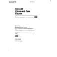
4-2. CIRCUIT BOARDS LOCATION
� Waveforms
(MODE:PLAY)
1
0V
DISC IN SW board
SUB board
Approx. 620mVp-p
tuner unit LIMIT SW board
IC2
1
(FEO)
2
1.2Vp-p
IC2
#¡
(RFO)
3
0V Approx. 200mVp-p
IC2
$�
(TEO)
4
2.6Vp-p
DISPLAY board
MAIN board
7.6µsec
IC1
LOAD SW board SERVO board
3
(MDP)
5
5.8Vp-p 22.7µsec
IC1
@º
(LRCK)
6
5.7Vp-p 474nsec
Note on Schematic Diagram: � All capacitors are in µF unless otherwise noted. pF: µµF 50 WV or less are not indicated except for electrolytics and tantalums. � All resistors are in � and 1/4 W or less unless otherwise specified. Note: The components identified by mark ! or dotted line with mark ! are critical for safety. Replace only with part number specified. � U : B+ Line. � H : adjustment for repair. � Power voltage is dc 14.4V and fed with regulated dc power supply from ACC and BATT cords. � Voltage and waveforms are dc with respect to ground under no-signal conditions. no mark : CD PLAY � : Impossible to measure � Voltages are taken with a VOM (Input impedance 10 M�). Voltage variations may be noted due to normal production tolerances. � Waveforms are taken with a oscilloscope. Voltage variations may be noted due to normal production tolerances. � Circled numbers refer to waveforms. � Signal path. J : CD
IC1
@�
(BCK)
7
3.2Vp-p 16.89MHz
IC1
#¢
(XTAI)
� 21 �
� 22 �
|
|
|
> |
|