|
There are currently no product reviews.
 ;
Once again, excellent price and manual delivered in a timely manner and as advertised!
;
Outstanding quality manual. This is the exact documentation I needed to service my AKAI GX-210D. This is a PERFECT COPY of the service manual for my machine. Outstanding service. Thank-you!
;
This service manual have great value... Recommended A+++++++
;
This service manual have great value... Recommended A+++++++
;
This service manual have great value... Recommended A+++++++
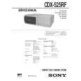
� FOCUS GAIN ADJUSTMENT (COARSE ADJUSTMENT) This adjustment is to be performed when replacing the following parts. � Optical Pick-up Block � RV14
[RF BOARD] � Conductor Side �
� When gain is lowered... The set does not play because of no focus operation. � When gain is highered... Operation noise is heard due to a scratch or a dust, then operation will be unstable.
RV14
IC51
CNJ12
IC11
Procedure: 1. Set RV14 (RF board) to the standard position. 2. Check that there is not an abnormal amount of operation noise (white noise) from the 2-axis devise. If there is, turn RV14 slightly clockwise.
[RF BOARD] � Conductor Side �
MIN side (low gain)
MAX side (high gain)
RV14 standard position
� 19 �
|