|
|
|
Categories
|
|
Information
|
|
Featured Product
|
|
|
 |
|
|
There are currently no product reviews.
 ;
I am really satisfied. It was ceap, easy and quick. Te owner manual is a full service book. I got what I expected. Thx
;
The service was good but it just a little late for the download. It seems that it needs to clear the payment but the payment was settled by paypal. As far as my concern, it should be able to download after the confirmation of sold.
;
Great quality manual, fast service, excellent seller... Thanks !!!
;
Great manual and fast service. Download was possible after a few hours.
;
thanks a lot.
without the service manual my handycam was going to the trash.
good job, go on.
bye
TUNER SECTION
0 dB = 1 µV
FM FREQUENCY COVERAGE Frequency Display Adjustment Part ADJUSTMENT 87.5 MHz 1.6 ± 0.4 V <confirmation> 108 MHz 4.0 ± 0.1V L2
� FM Section Setting: RADIO (BAND) button: FM
FM RF signal generator TP (FM ANT) 0.01 µF
set
75 kHz frequency deviation by 1 kHz signal output level : as low as possible
Reading on Digital voltmeter
FM TRACKING ADJUSTMENT Adjust for a maximum reading on level meter. L1 87.5 MHz CT1 108 MHz
AM FREQUENCY COVERAGE CHECK � AM Section Setting: RADIO (BAND) button: AM
AM RF signal generator Put the lead-wire antenna close to the set.
Frequency Display Reading on Digital voltmeter Adjustment Part
530 kHz 1.0 + 0.7 V � 0.5 V
1,710 kHz 4.8 + 1.2V � 0.6 V
<confirmation> <confirmation>
AM TRACKING ADJUSTMENT Adjust for a maximum reading on level meter. L4 620 kHz CT3 1,400 kHz
30% amplitude modulation by 400 Hz signal
� For AM adjustment, fix the ferrite-rod antenna (L3) as shown below and then perform tracking adjustment at L4 and CT3. Lastly check the voltage.
3.0 ± 1.0 mm
level meter (range: 0.5�5 V ac) 32 �
� Connecting Level Meter (FM and AM)
set
2 jack (J301)
L3 AM FERRITE-ROD ANTENNA
Adjustment Location: See page 14. � Connecting Digital Voltmeter (FM and AM)
digital voltmeter 100 k� TP (VT) (JW17)
� Repeat the procedures in each adjustment several times, and the frequency coverage and tracking adjustments should be finally done by the trimmer capacitors.
� 13 �
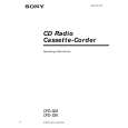 $4.99 CFD-S38 SONY
Owner's Manual Complete owner's manual in digital format. The manual will be available for download as PDF file aft…
|
|
|
> |
|