|
|
|
Categories
|
|
Information
|
|
Featured Product
|
|
|
 |
|
|
There are currently no product reviews.
 ;
Bon produit. Permet de corriger les couleurs et de redonnez un petit coup de jeune à vos vieilles vidéos. On regrettera juste le manque d'une prise s-vidéo.
 ;
Quality scan of the actual service manual, just what I was looking for.
;
Straightforward ordering process. Service manual scan was clear & easy to read. Very comprehensive instructions for alignment. Excellent, thank you.
;
Fast, clear and useful. Important for me: the manual is in German.
;
Very good quality. Some parts are not fully readable, but the fundamental ones are fine.
CD SECTION
Notes on Check 1. Perform the traverse check in the CD test mode. 2. 3. After check, be sure to exit the test mode. Perform check in the order given. Use the disc (YEDS-18, Parts No. 3-702-101-01) only when so indicated.
E-F Balance Check Adjustment Location : MAIN board (See page 23) This check is to be done when the optical pick-up block is replaced. Check Procedure: 1. Connect the oscilloscope to test point TP (VC) and TP (TE) on MAIN board. 2. Put the set into test mode. 3. Optical pick-up setting to the center by + or = button pushing. 4. Insert disk (YEDS-18) and press ^ button. 5. Check that the oscilloscope traverse waveform is symmetrical, as shown in the figure below. 6. Release test mode after adjustment is completed.
Before Check Put the set into test mode and perform the following checks. Repair if there are any problems. � Sled Motor Check Press + , = keys and confirm that the Optical pick-up moves smoothly from the innermost to outermost circumference and back smoothly and with no catching or abnormal noises. (Cancellation of BTL mute) + : Optical pick-up moves to the outer circumference. = : Optical pick-up moves to the inner circumference. � 1. 2. Focus Search Check Press the CD ^ key. (Focus search operation is performed continuously.) Look at the Optical pick-up objective lens and confirm that it moves up and down smoothly, with no catching or abnormal noises. Press p button. Confirm that focus search operation stops. If it does not, press p button again longer.
A 0V B A=B C = 500mV ± 100mV C
VOLT/DIV : 0.1V TIME/DIV : 1ms
[MAIN BOARD]
3.
How to Enter the Set into Test Mode 1. Turn the AC CORD IN (Adaptor). (LCD 501 indicator blinks the test mode pattern.) 2. Short-circuit between the lands as shown on the control (1) board. How to Exit the Test Mode Turn the POWER OFF.
TP(FE) TP(VC)
TP(TE)
[CONTROL (1) BOARD]
TP(RF)
Osilloscope (DC range) TP(TE) TP(VC)
+ �
Jumper wire Test portion Short : Test mode Open : Normal mode
� 14 �
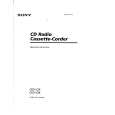 $4.99 CFD-V25 SONY
Owner's Manual Complete owner's manual in digital format. The manual will be available for download as PDF file aft…
|
|
|
> |
|