Shopping cart is empty
 
English Polski Spanish 
Search For a Manual
 

(e.g. AA-V20EG JVC, ZX-7 Sony )
PayPal 1000+ rating Secure, Encrypted Checkout.
 
Categories
Information
Featured Product
Home >> SONY >> CFMA50 Service Manual
 
 0 item(s) in your cart 

SONY CFMA50
Service Manual


Tweet about this product and get $1.00 of store credit for instant use!
  • Contains Circuit Diagrams
  • Download
  • PDF Format
  • Complete manual
  • Language: English
Price: $4.99

Description of SONY CFMA50 Service Manual

Complete service manual in digital format (PDF File). Service manuals usually contains circuit diagrams, printed circuit boards, repair tips, wiring diagrams, block diagrams and parts list. Service Manual ( sometimes called Repair Manual ) is used mainly by technicians.

If You just want to know how to use Your tv, video, mp3 player etc. You should look for Owner's Manual. After placing order we'll send You download instructions on Your email address.

The manual is available in languages: English

Not yet ready
You must purchase it first

Customer Reviews
There are currently no product reviews.
Other Reviews
 KA-3060R KENWOOD Service Manual by Christian Wiebel;
It is great, it saves money and paper. It helps me to save room and recources.
 KA-5050R KENWOOD Service Manual by marculet viorel;
manual service is ok , resolve the problems manual service is ok , resolve the problems manual service is ok , resolve the problems manual service is ok , resolve the problems manual service is ok , resolve the problems
 STRK850P SONY Service Manual by Roberto Ponce;
Well I got all the necessary specifications for the job. Document of good quality and good definition of the diagrams
 GRVF1EG JVC Service Manual by koprintziotis nikolaos;
hi .full information for JVC GRVF1EG Service Manual its compete .Thank You
 7000 NAD Service Manual by ronald bokschoten;
perfect and good copies, all good readable. within 24hrs and very cheap also.

Text excerpt from page 7 (click to view)
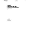
SECTION 3 DIAL POINTER SETTING
Note : Follow the instaooation procedure in the numerical order given.
1 Attach TU worm to tuner chassis. 2 Attach needle, tighten needle spring using a bolt, then attach TU

LED board. 3 Rotate TU worm until needle stops at the stopper shown in Fig. A.

2 Pointer

Screw (+P 2.6x5)

Fig. A

Retainer, Pointer
4 Plate, blind

Stopper

Fig. B

5 Knob, band

Chassis, TU

TUN LED board
4 Mount PLATE BLIND and position it as shown in Fig. B. 5 Attach the band knob. Make sure that the projected part of the
1 Worm, TU

tuner chassis fits as shown in Fig. C (the arrow).
3

Fig. C

6 Tighten idler gear, combine projected part of band knob and the

band slider so that they interlock, then mount to main board. 7 Mount VR gear to main board, then turn in the direction of the arrow until it stops. 8 Fasten the TU gear to the TU chassis with the screw.
8 Gear, TU

Screws (+BV 3x10)

Screw (+BV 3x10)

Main board

Slieder, band

Screw (+B 2.6x5)

Chassis, TU

7 Gear, VR

Screw (+BV 3x10)

6 Gear, idler

�7�

You might also want to buy

$4.99

CFM-A50 SONY
Owner's Manual

Complete owner's manual in digital format. The manual will be available for download as PDF file aft…
>
Parse Time: 1.066 - Number of Queries: 101 - Query Time: 0.477