|
|
|
Categories
|
|
Information
|
|
Featured Product
|
|
|
 |
|
|
There are currently no product reviews.
 ;
It´s very very nice manual with all, what i need. Original in good quality. Very fast business. Very much thanks...
;
Purchased the manual that I was looking for at a great price and could download it easily.. Great service experience and for future purchases I plan to use the site.
Thank you very much
;
Exactly what was needed to assess the product - excellent value and great service
;
A site where discontinualed schematic diagrams and back dated information can be found on discontinued radios tv's and any electronic equipment can be found. Newer manuals either Service and operating manuals. Radio amateurs should find this site a great source for ham radio equipment manuals. I will return to this site should I need information on any electrical equipment. priced easy to download in a PDF format and print pages need to undertake the repair.
;
Quality scan of the original. All the detail necessary to troubleshoot, repair and adjust the unit. I'm sure I will be downloading more manuals in the future as the need arises.
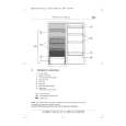
27L-S100/27L-S180 CL27S10/CL27S18
INSTALLATION AND SERVICE INSTRUCTIONS
Note: (1) When performing any adjustments to resistor controls and transformers use non-metallic screwdrivers or TV alignment tools. (2) Before performing adjustments, the TV set must be on at least 15 minutes.
CIRCUIT PROTECTION The receiver is protected by a 4.0A fuse (F701), mounted on PWB-A, wired into one side of the AC line input. X-RADIATION PROTECTOR CIRCUIT TEST
After service has been performed on the horizontal deflection system, high voltage system, B+ system, test the X-Radiation protection circuit to ascertain proper operation as follows: 1. Apply 120V AC using a variac transformer for accurate input voltage. 2. Allow for warm up and adjust all customer controls for normal picture and sound. 3. Receive a good local channel. 4. Connect a digital voltmeter to TP653 and make sure that the voltmeter reads 11.2 ± 0.6V. 5. Apply external 13.8V DC at TP653 by using an external DC supply, TV must be shut off. 6. To reset the protector, unplug the AC cord and make a short circuit between TP651 and TP652. Now make sure that normal picture appears on the screen. 7. If the operation of the horizontal oscillator does not stop in step 5, the circuit must be repaired before the set is returned to the customer.
HIGH VOLTAGE CHECK
High voltage is not adjustable but must be checked to verify that the receiver is operating within safe and efficient design limitations as specified checks should be as follows: 1. Connect an accurate high voltage meter between ground and anode of picture tube. 2. Operate receiver for at least 15 minutes at 120V AC line voltage, with a strong air signal or a properly tuned in test signal. 3. Enter the service mode and select the service adjustment "S19" and Bus data "01" (Y-mute on). 4. The voltage should be approximately, 28.7kV (at zero beam). If a correct reading cannot be obtained, check circuitry for malfunctioning components. After the voltage test, make Y-mute off to the normal mode.
8
|
|
|
> |
|