|
There are currently no product reviews.
 ;
THANK YOU FOR A GOOD TRANSACTION, NICE COPY, CLEAR
;
Very Good! All the diagram are easy to read, and its complete.
;
This was an excellent source of detailed assembly information on a device which is at least 12 years old. A very lucky find, coupled with great service.
;
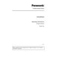
Excellent Service Manual and best price on the Internet. This Service Manual covers everything you could ever need including full circuit schematics, component layout diagrams, stripdown procedure and full parts list/breakdown. I needed this to carry out a modification to one of these headunits and this manual covered everything I needed. Fast delivery, processed within a few hours.
 ;
Thought I would never find a copy of the Technics SX-EN2 Service Manual until I found Owner-Manuals.com. Price was very fair and I received the download promptly. While a photocopy, it is quite readable and includes all the pertinent information and diagrams. Thank you Owner-Manuals!
Vcc 2
VCC Rpull-up* VCC
Magnetic Sensor-1 gain Initialization Coils XY-chip A/D
T1 16
Powerdown Control
15 VDD1 7 IOVDD1 8 SCL1 14 SDA1
Serial Data Interface Clock Generator (Resisters) Power on Reset
G696/G697
P
RESET INPUT GND
Magnetic Sensor-2
CD 5
CD
RESET (RESET) GND
6 VSS1
Magnetic Sensor-3 gain
Z-chip
Powerdown Control Serial Data Interface
28 VDD2 20 IOVDD2 21 SCL2 22 SDA2
*G697 ONLY
Initialization Coils
A/D
1
U4
3
Temperature Sensor Clock Generator
GND
(Resisters) Power on Reset
18 VSS2
1 I1
2 I2
3 I3
19 T2
A
1
5
Vcc
U13
B
2
GND
3
4
Y
U5
VS
14,15
ADXL330
OUTPUT AMP 3-AXIS SENSOR AC AM P DEMOD OUTPUT AMP
RFILT
12 X OUT
RFILT
10 YOUT
RFILT OUTPUT AMP
8 Z OUT
3,5,6,7
COM
2
ST
U12
12
|