|
|
|
Categories
|
|
Information
|
|
Featured Product
|
|
|
 |
|
|
There are currently no product reviews.
 ;
I was having a hard time finding the problem with this Mackie 1604 unit. I didn't have a schematic. Went looking on the web and found your site and the price was more then reasonable. Ordered it and within the hour had the manual and within 15 minutes had the unit fixed. Best $4.99 I ever spent. Thank you.
Doug
;
This is a service manual in every sense of the word ( French and German versions of the text are included, as well as English..)
There are explanations of the mechanical and electrical functions, plenty of mechanical drawings, and the needed schematics. The quality of the scanning is excellent - all the component values are clearly legible - and very usefully there are pcb component layouts, so you can find a component on the schematic, and then very quicky pinpoint its physical location on the relevant pcb.
I cannot see how I can give this manual any less than the maximum 5 stars! Great value for money, which will pay for itself immediately. Excellent all round!
;
the manual is great and especially hard to find... thanks for the great service and having a hard to find manuel_
;
Please tell us what you think and share your opinions with others. Be sure to focus your comments on the product. You will receive $2.50 of store credit for Your review.
;
hat alles sehr gut geklappt. Das Servicemaual ist gut zu verwenden. Die Pläne und Schrift
ist klar und leserlich. Außerdem preiswert. Grüße an alle Hifi-Bastler
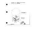
CHAPTER 6 FIXING SYSTEM
C.
Protecting the Fixing Assembly
The printer unit is equipped with the following three types of protective mechanisms to prevent malfunction of the fixing heater: � The M-CPU monitors the voltage of the upper fixing roller temperature detection signal (FXTHU) and the lower fixing roller temperature detection signal (FXTHL). If either or both incur an error, the M-CPU will identify the condition as a fixing heater fault, and will communicate the fact to the printer board*1 to cut off the power to the heaters. � If the fixing temperature increases abnormally and, as a result, either or both upper and lower thermistor (THU, THL) readings exceed about 230°C, the safety circuit will cut off the power to the heaters regardless of the output of the M-CPU. At the same time, the M-CPU identifies the condition as a power supply fault, and communicates the fact to the printer board1 by way of the D-CPU. � If the fixing temperature increases abnormally and, as a result, the temperature of either or both upper and lower thermal switch exceeds about 240°C, the upper/lower thermal switch will turn off to cut off the power to the fixing heaters. *1 Reader controller PCB (when making prints with the reader unit installed). Note: To reset the printer unit after a fixing heater error has been stored in the error memory capacitor (C259), turn it off and then on after leaving it alone for 30 min or more.
D.
Detecting a Fault in the Fixing Assembly
A fault in the fixing assembly is checked by the following three: 1. M-CPU on the DC controller PCB 2. Fixing heater safety circuit (in the power supply circuit) 3. Fixing assembly error detection circuit (in the power supply circuit) Details follow.
1. M-PCU on the DC Controller PCB If the fixing assembly is abnormally heated or it fails to reach a specific temperature, the M-CUP uses the D-CPU to stop the operation of the fixing heater, and cut the relay (RL101) to shut off the power to the fixing heater. The DC controller then communicates the fault in the fixing heater to the printer board*1. Specifically, the M-PCU detects a fault in the fixing heater under any of the following conditions: a. A fixing assembly error is stored in the error memory capacitor (C259) on the DC controller PCB at time of power-on. (error low temperature E003 or error high temperature E001) b. The increases in temperature are monitored every 20°C from 20°C to when the standby temperature is attained after the fixing heater is driven; the time required is compared against the reference time, and the time required is longer than the reference time. c. The fixing assembly temperature drops below 120°C after it has reached the target level. (error low temperature E003) d. The fixing temperature reaches about 230°C or more during standby or during copying. (error high temperature E001; Note 1) 6-4
COPYRIGHT © 1999 CANON INC. CANON 660/2100 REV.0 FEB. 1999 PRINTED IN JAPAN (IMPRIME AU JAPON)
 $4.99 CP660 CANON
Parts Catalog Parts Catalog only. It's available in PDF format. Useful, if Your equipment is broken and You need t…
|
|
|
> |
|