|
|
|
Categories
|
|
Information
|
|
Featured Product
|
|
|
 |
|
|
There are currently no product reviews.
 ;
I ordered this manual sometime in the afternoon and I received it on my e-mail the same evening.
This is a fantastically good and properly scanned copy of the original manual. All pages are of the same scale and they overlap each other. It means that you can print the manual and easily make it as a convenient paper manual.
The content of the manual is fantastic. Alignment descriptions, PCB layouts and elementary diagrams are explicit and precise. I immediately found what I was looking for. Thanks to this manual and Owner-Manuals.com my amplifier is alive again. Many thanx indded!
;
The manual was well-scanned and easy to read. As an added bonus, the Operator's Manual was bundled with the Service Manual!
I'd definitely use owner-manuals.com again.
;
Finally, i found one website, where i can download this service manual , and fix my hifi. The service manual is very good, and easy to download and to print.
 ;
Complete and very useful. Could have benefited from a little higher resolution on the schematic and layout diagrams for improved legibility.
;
Great Service Manual, Very Complete, as advertised, Perfect, Thanks!
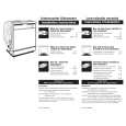
Wiring of the circuit power supply (2/2) Wiring of the circuit power supply board (1)Style the CNPOW, TSW, and FG3. (2)Attach the CNSH2 (3)Attach the power supply sheet. (4)Style the CNPWR.
TSW Fastener
Lock the CNPOW, TSW, and FG3 by passing them through the power supply case fastener.
Make sure to pass the CNSH2 through the hole indicated in the diagram below. [CAUTION] Make sure to attach the power supply sheet after attaching the CNSH2.
Power supply case
CNPOW
FB5
Pass the CNPWR through the hole in the power supply sheet, and pull the wire out. When pulling out the CNPWR and FB2, make sure that they do not pass over the C104 (electrolytic capacitor), as this will cover the anti-explosion valve on the top of the capacitor.
View from above
C104
CN102
FG3 Power supply sheet CN103 C104 FG1
FB1
CP-S240(CC9SM)/CP-X250(CC9XM)
Circuit power supply
CN101 FB2 CNSH2
E2
31
View from the side
C104
Fasten the CNSH2 and E2 with tape, ZTP1 and ZTP2, after passing them through the clamps of the power supply case. [CAUTION] As the upper case touches the gray areas of the diagram on the right, make sure no wires protrude into these areas.
CNPWR
ZTP2
Clamp Clamp
Power supply sheet
Power supply sheet
C104
C104
Correct (solid line) Correct Incorrect
Louver of the power supply case Incorrect (dotted line)
Outline of power supply case holes
Don�t wire the E2 on the louvers. The solid line in the diagram indicates an example of correct wiring. The dotted lines in the diagram indicate examples of incorrect wiring.
ZTP1
Fasten the E2 with tape ZTP1. Make sure to stick the tape along the outline of the power supply case holes as shown in the diagram.
Wiring diagram 2
|
|
|
> |
|