|
|
|
Categories
|
|
Information
|
|
Featured Product
|
|
|
 |
|
|
There are currently no product reviews.
 ;
I purchased the unit from a private party and the original owners manual was not available. Having the ability to download it was extremely helpful and clarified operating the equipment immensely. This is a complicated unit and without the manual I would not have been able to maximize it's potential. Thank you.
;
Being a user of older radios of many kinds, preferring them over more modern rigs, this manual was invaluable in the programming of my two. I now know for certain what the assorted buttons functions are, and am very grateful to have found this excellent site. Many thanks for your assistance, Tony.
 ;
Clear and easy to read. All details as expected. Price acceptable , and quick delivery.
;
Quick response and exactly what I was looking for and at a great fair price!
;
5 star quality on these downloadable manuals. Easy to read and all the information is there. A must when doing a custom install or needing to service your precious old school electronics.
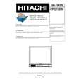
LOCATION AND OPERATION OF CONTROLS
1. TINT
Adjust the TINT control for the proper color phase or flesh tones. When turned counterclockwise, the skin tone becomes reddish. When turned clockwise, skin tone becomes greenish.
2. SHARPNESS
Adjust the SHARPNESS control to obtain the clearest picture.
3. COLOR
Adjust the COLOR control to set the color saturation level. Turn the control clockwise to increase and counterclockwise to decrease.
4. BRIGHTNESS
Adjust the BRIGHTNESS control for the desired overall display brightness. This control is also useful to compensate for differences in area lighting. Turn the control clockwise to increase and counterclockwise to decrease.
5. CONTRAST
Adjust the CONTRAST control for the desired overall contrast. Proper adjustment will allow maximum gradations between the darkest and lightest picture areas. Turn the control clockwise to increase and counterclockwise to decrease.
6. VOLUME
Adjust the VOLUME control for the desired audio level. Turn the control clockwise to increase and counterclockwise to decrease.
7. VIDEO 1 SWITCH
Set the switch to VIDEO 1 if the camera jack is used.
8,10,12. VIDEO LED LAMP
VIDEO lamps indicater video mode in selected.
9. VIDEO 2 SWITCH
Set the switch to VIDEO 2 if the camera jack is used.
11. Y/C SWITCH
Set the switch to S-VHS if the S-VHS jack is used.
13. POWER SWITCH
Press to turn the monitor ON. The POWER LAMP above the switch will illuminate.
14. POWER LED LAMP
Power lamp indicates the power is on.
15. POWER INLET
Use 100-240V AC, 50/60 Hz. To prevent electrical shocks and fire hazards, do not use any other power source.
16,17. IMPEDANCE SWITCH
Set the switch to the HIGH position if the VIDEO OUTPUT jack is used. The last monitor should be set in the 75 position. Set the switch to the 75 position if the VIDEO OUTPUT is not used.
18
21. VIDEO INPUT & OUTPUT CONNECTORS
These BNC connectors permit looping of a video signal in those installations where it is desirable to display the video signal on more than one monitor. A standard 1.0 Vp-p video signal applied to the VIDEO INPUT will also appear at the VIDEO OUTPUT. Use coaxial cables with BNC type plugs for these connections.
22. S-VHS JACK
If your input is S-VHS (VIDEO), connect directly to this jack.
23
26. AUDIO INPUT & OUTPUT CONNECTORS
Connect an RCA cable between these jacks and the audio output jack of a camera or VCR.
7
|
|
|
> |
|