|
There are currently no product reviews.
 ;
The manual is very good quality. very good graphics. complete
;
Excellent printing quality.
A complete and very usefull service manual with all details.
GREAT SERVICE AT VERY LOW PRICE!
A+++++++++++++++++++++++++
;
Excellent, very professional, fast, reliable, congratulations thank you.
;
Excellent printing quality.
A complete and very usefull service manual with all details.
GREAT SERVICE AT VERY LOW PRICE!
A+++++++++++++++++++++++++
;
Excellent printing quality.
A complete and very usefull service manual with all details.
GREAT SERVICE AT VERY LOW PRICE!
A+++++++++++++++++++++++++
â� PIN FUNCTIONS
PIN No. 5 6 8 10 11 12 13 14 15 16 19 27 28 29 30 31 32 43 44 52 53 NAME VFD_CS VFD_CLK VFD_DATA DATA CLK VDD 1 VSS 1 X OUT X IN TEST VFD_RESET DATA 3 DATA 2 DATA 1 DATA 0 CS CLK AVREF AVSS VSS 2 VDD 2 I/O O O O I I I I I I I I I I FIP data output port FIP driver IC(IC42) chip enable port FIP driver IC(IC42) clock in/out port A/D converter reference voltage A/D converter ground Power input port GND Pull - down register connected internally VFD Reset port FIP data in/out port FIP data input port VFD STB port VFD Clock port VFD data port UPDATE data port UPDATE clock port Power input port GND 10MHz Crystal Connection port DESCRIPTION
�10�
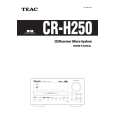 $4.99 CRH250 TEAC
Owner's Manual Complete owner's manual in digital format. The manual will be available for download as PDF file aft…
|