|
|
|
Categories
|
|
Information
|
|
Featured Product
|
|
|
 |
|
|
There are currently no product reviews.
 ;
Excellent service manual with all the necessary info. :)
 ;
The product dowload was delivered efficiently with emails to support its download availabilty. The contets of the manual was very eligible and of good quality. Will purchase from this site again!
;
hello this Service Manual PIONER KXE60 is very good, thanks.
;
It was just what I needed. Thanks for your quick action and great price. You guys are top notch.
Thanks
;
Excellent manual, complete, great resolution, easy to read especially the schematics. Thank you !
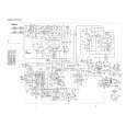
ELECTRICAL ADJUSTMENT
PRACTICAL SERVICE FIGURE
MAIN C.B
6
2
66 7 2
< TAPE RECORDER SECTION >
(ALL MODEL)
8. Tape speed Adjustment Condition: � Test tape: TTA-100 � Test point: PHONES JACK Method: � Adjustment location: SFR of deck motor Play back the test tape and adjust so that the output frequency is 3000Hz.
< RADIO SECTION >
Sensitivity: (IHF, THD 3%) (S/N 20dB) (S/N 20dB) (S/N 20dB) Intermediate frequency: FM stereo separation: FM Less than 25dB MW Less than 60dB LW Less than 66dB (200kHz) <EZ> SW Less than 40dB (8MHz) <HRJ> FM 10.7MHz AM 455kHz More than 20dB (1kHz)
EZ MODEL TC101 L102 HRJ MODEL
5
TC4 TC1 TC2 L108 Method:
9. Azimuth Adjustment Condition: � Test tape: TTA-320 � Test point: PHONES JACK � Adjustment location:Azimuth adjustment screw Play back the test tape and adjust so that the output is maximum.
< TAPE RECORDER SECTION >
Distortion: S/N ratio: Erasing ratio: Wow & Flutter: Take-Up Torque: F.F & REW Torque: Test tape: Less than 3% (PB, 1kHz) Less than 8% (REC/PB, 1kHz) More than 40dB (PB, REC/PB, AC, DC) More than 30dB Less than 0.35% (RMS) 20-60g-cm (FWD, REV) 55-120g-cm TTA-100 NORMAL TTA-602 TTA-210 TTA-257
L102 EZ MODEL
L101 TC102 L104 L109 L105 TC3
L107
L301
10. AC Bias Adjustment Condition: � Test tape: TTA-630 � Test point: TP1 � Adjustment location: L301 Method: Set up the recording mode. Adjust L301 so that the TP1 becomes 70kHz.
0
3
1
M3
4
< RADIO SECTION >
(HRJ MODEL)
1. MW/SW IF Adjustment L109 ....................................................................... 455kHz 2. MW Tracking Adjustment L101 ....................................................................... 600kHz TC4 ....................................................................... 1400kHz 3. MW Frequency Range Adjustment L104 ....................................................................... 515kHz TC102 ................................................................... 1650kHz 4. FM Tracking Adjustment L107 ........................................................................ 88MHz TC2 ........................................................................ 106MHz 5. FM Frequency Range Adjustment L108 ........................................................................ 87MHz TC1 ........................................................................ 109MHz 6. SW Tracking Adjustment L102 .......................................................................... 4MHz 7. SW Frequency Range Adjustment L105 ....................................................................... 3.8MHz TC3 ....................................................................... 12.5MHz
8
(EZ MODEL)
9
1. MW/SW IF Adjustment L109 ....................................................................... 465kHz 2. LW Tracking Adjustment L101 ....................................................................... 160kHz TC4 ......................................................................... 295kHz 3. LW Frequency Range Adjustment L104 ....................................................................... 145kHz TC102 ..................................................................... 295kHz 4. FM Tracking Adjustment L107 ........................................................................ 88MHz TC2 ........................................................................ 106MHz 5. FM Frequency Range Adjustment L108 ........................................................................ 87MHz TC1 ........................................................................ 108MHz 6. MW Tracking Adjustment L102 ....................................................................... 600kHz TC101 ................................................................... 1400kHz 7. MW Frequency Range Adjustment L105 ....................................................................... 515kHz TC3 ....................................................................... 1635kHz
13
14
|
|
|
> |
|