|
|
|
Categories
|
|
Information
|
|
Featured Product
|
|
|
 |
|
|
There are currently no product reviews.
 ;
Excellent quality, very quick download turnaround, will definately use again.
 ;
This is a awesome quality scan of the original Service Manual for Technics 8099.
Contains the circuit diagram, PCB layout, adjust/tune instructions as well.
Since this is my first buy here, i'm really glad! This site do works as intended/described, it's definitely not scam!
Мои рекомендации! Все мануалы настоящие!
;
Good Quality of the File.
You get the normal manual is incudet.
;
Very nice and real Service Manual, I didn't thought it actually exist in the real world at all.
;
VERY NICE FOR COURTESY AND PRECISION!.
tHE SITE IS VERY IMPORTANT FOR ALL DEVICES
vERY GOOD
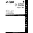
IC, LA9241ML Pin No.
1 2 3 4 5 6 7 8 9 10 11 12 13 14 15 16 17 18 19 20 21 22 23 24 25 26 27 28 29 30 31 32 33 34 35 36
Pin Name
FIN2 FIN1 E F TB TE� TE TESI SCI TH TA TD� TD JP TO FD FD� FA FA� FE FE� AGND SP SPI SPG SP� SPD SLEQ SLD SL�
I/O
O
Description
For the connection of the pickup photodiode. Addition to the FIN1 pin creates an RF signal and subtraction from it create an EF signal.
O O
For the connection of the pickup photodiode. For the connection of the pickup photodiode. Subtraction from the F pin creates a TE signal.
O I O
For the connection of the pickup photodiode. Inputs the DC components in the TE signal. For the connection of a resistor which sets the gain of the TE signal between this pin and the TE pin.
O I I I O I O I O O I O I O I
TE signal output. TES (track error sense) comparator input.The TE signal is passed through a BPF. Shock detection input. Sets the time constant for the tracking gain. TA amp output. Composes the tracking phase compensation constant between the TD and VR pins. Sets the tracking phase compensation. Sets the amplitude of the tracking jump signal (kick pulses). Tracking control signal output. Focusing control signal output. Composes the focusing phase compensation constant between the FD and FA pins. Composes the focusing phase compensation constant between the FD- and FA- pins. Composes the focusing phase compensation constant between the FA and FE pins. FE signal output. For the connection of a resistor whichs sets the gain of the FE signal between this pin and the TE pin.
O O I I I O I O I
Ground of analog signals. Single-ended output of the signals input to the CV+ and CV- pins. Spindle amp input. For the connection of a resistor which sets the gain in the spindle 12cm mode. For the connection of the spindle phase compensation constant with the SPD pin. Spindle control signal output. For the connection of sled phase compensation constant. Sled control signal output. Sled feed signal input from the microprocessor.
SL+ JP� I JP+ TGL TOFF TES I I O Tracking gain control signal input from the DSP. Low gain when TGL is "H". Tracking off control signal input from the DSP. Off when TOFF is "H". Outputs the TES signal to the DSP. Tracking signal input from the DSP.
� 22 �
|
|
|
> |
|