|
|
|
Categories
|
|
Information
|
|
Featured Product
|
|
|
 |
|
|
There are currently no product reviews.
 ;
muy buen manual por lo completo de este algunos esquemas estan muy divididos lo que hace algo dificil el seguimiento.
;
very good manual, with detail and clarity in esquematic diagrams and waveforms .
 ;
Very quality copy of original service manual, which contains the circuit diagrams, PCB and lists of components, well as recommendation for calibration procedures of device, also everything else, that need for repair, tuning and use this oscilloscope.
All presented copies have high-resolution, so you can view all in detail.
This manual will very useful for simple owners and for repairers.
I recommend these manual, because myself is owner of Philips PM3216 and I need sometimes servicing these oscilloscope (principally calibrating).
Also, these document is an example of excellent design of technical documentation.
;
Excellent printing quality.
A complete and very usefull service manual with all details.
GREAT SERVICE AT VERY LOW PRICE!
A+++++++++++++++++++++++++
;
manual excelente completo , diagramas y esquemas bien presentados y buena calidad de imagen.
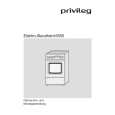
B CD C.B
TP4
1
IC404
TP3
IC401
1
SFR430
A MAIN C.B
L801
TP2
2
3
< CD SECTION >
1. Focus Bias Adjustment Make the focus bias adjustment when replacing and repairing the optical block.
Oscilloscope (DC range)
EYE PATTERN must be CLEAR and MAX VOLT / DIV: 200mV TIME / DIV: 0.5µs MAX
0V
+
TP3 (RF) TP4 (VREF)
< TAPE RECORDER SECTION >
2. Bias Adjustment � Test tape: TTA-630 � Test Point: TP2 � Adjustment location: L801 � Method: L801 .............................................................. 85kHz±2kHz 3. Azimuth Adjustment Condition: � Test tape: TTA-320 � Test point: PHONE JACK � Adjustment location: Azimuth adjustment screw Method: Play back the test tape and adjust the screw so that the output is maximum.
-
1) Connect an oscilloscope to the test point TP3 (RF) and TP4 (VREF). 2) Turn on the power switch. 3) Insert test disc TCD-782 (YEDS-18) and play back the second composition. 4) Adjust SFR430 so that RF signal of the test point TP3 (RF) is MAX and CLEAREST.
� 24 �
|
|
|
> |
|