|
|
|
Categories
|
|
Information
|
|
Featured Product
|
|
|
 |
|
|
There are currently no product reviews.
 ;
We needed a manual quickly...online it was available immediately, at a very low price. We loved the convenience!
;
Excellent!!
Got what I need and very fast!!
Thank You
;
One address for rare manuals.Very good copy. Thank you.
Your
Klaus Husse
;
All ok. I pay 5 $ and now i have 92 pages of good scaned service manual for my oooooold akai. Now i will try to repair it.
;
good and ok, very nice , good and ok, very nice, good and ok, very nice
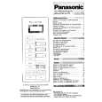
B CD C.B
TP4
1
IC404
TP3
IC401
1
SFR430
A MAIN C.B
L801
TP2
2
3
< CD SECTION >
1. Focus Bias Adjustment Make the focus bias adjustment when replacing and repairing the optical block.
Oscilloscope (DC range)
EYE PATTERN must be CLEAR and MAX VOLT / DIV: 200mV TIME / DIV: 0.5µs MAX
0V
+
TP3 (RF) TP4 (VREF)
< TAPE RECORDER SECTION >
2. Bias Adjustment � Test tape: TTA-630 � Test Point: TP2 � Adjustment location: L801 � Method: L801 .............................................................. 85kHz±2kHz 3. Azimuth Adjustment Condition: � Test tape: TTA-320 � Test point: PHONE JACK � Adjustment location: Azimuth adjustment screw Method: Play back the test tape and adjust the screw so that the output is maximum.
-
1) Connect an oscilloscope to the test point TP3 (RF) and TP4 (VREF). 2) Turn on the power switch. 3) Insert test disc TCD-782 (YEDS-18) and play back the second composition. 4) Adjust SFR430 so that RF signal of the test point TP3 (RF) is MAX and CLEAREST.
� 24 �
|
|
|
> |
|