|
|
|
Categories
|
|
Information
|
|
Featured Product
|
|
|
 |
|
|
There are currently no product reviews.
 ;
I searched EVERYWHERE looking for the manual/s on this "extinct" amp. Owner-Manuals.com made it available and for nearly nothing. Thanx to them, I can decipher the unknown cables and sort them out. Thanx, Owner-Manuals.com!!
;
Yes thank you i got the file i was after. There was a slight problem in my communication but it all worked out well.
A job well done.
 ;
Great manual...really saved me. The only problem is that I thought I would be able to download it directly when I paid for it but never received the download instructions until the next morning. The board trace pages were somewhat light also: really need to turn up the contrast on the printer before printing them. The schematic page was great; very clear! Well worth the money.
;
I've been in the electronic business for a long time. I used to buy Sam's Photofact for my needs which intailed having to go to the store and paying about $20 for a package of 3 different units so I was forced to buy more than I needed just to get one.
Owner manual is just at your keyboard and the information is almost instantansouly and the cost is very reasonable. Easy to print out if needed or simply read off of the screen. The larger the screen the better for obvious reasons.
;
Very good manual, at a very good price. Received in a timely manner
IC DESCRIPTION IC, LC78622E
Pin No. 1 2 3 4 5 6 7 8 9 10 11
12, 13
Pin Name DEFI TAI PDO Vvss ISET VVDD FR Vss EFMO EFMIN TEST2 CLV+, CLK� VIP HFL TES TOFF TGL JP+, JP� PCK FSEQ VDD
I/o I I o � For PLL. I � I � o I I 0 o I I o o 0 o o
Description Defect sense signal (DEF) input pin. (Connect to OVwhen notused). Testsignalinput pinwithbuilt%pull-dow nresistor. esureto connecttoOV. B
Phase comparator output pin to control external VCO. GNDpinfor built-in VCO. Besureto connect toOV. Pin to which external resistor adjusting the PDO output current. Power supply pin for built-in VCO. Pin for VCO frequency range adjustment. Digital system GND. Besureto connect toOV. For slice leyel control. EFM signal output pin. EFM signal input pin. Test signal input pin with built-in pull-down resistor. Be
sure to connect to OV.
Disc motor control output. Three level output is possible using command. Rough servo or phase control automatic selection monitoring output pin. Rough servo at H. Phase servo at L.
14 15 16 17 18 19,20 21 22 23
Track detect signal input pin. Schmidt input. Tracking error signal input pin. Schmidt input. Tracking OFF output pin. Tracking gain selection output pin. Gain boost at L. Track jump control signal output pin. Three level output is possible using command. EFM data playback clock monitoring pin 4.3218 MHz when phase is locked in. Sync signal detection output pin. H when the sync signal which is detected from EFM signal and thesync signal which is internally generated agree. Digital system power supply pin. The pin is controlled by the serial data command from microprocessor. When
24-28
CONT1-CONT5
I/o
General purpose input/output pin 1 to 5.
the pin is not used, set the pinto the input terminal and connect to OV,or alternately set the pin to output terminal and leave the pin open.
29
30
EMPH
C2F
o
o
De-emphasis monitor output pin. De-emphasis disc is being played back at H.
C2 flag output pin.
31 32,33 34 35 36 37 38
39
DOUT TEST3, TEST4 N.C. MUTEL LVDD LCHO LVSS RVSS RCHO RVDD MUTER
o I
DIGITAL OUT output pin. (EIAJ format). Test signal input pin with built-in pull-down resistor. Be sure to connect to OV. Not used. Set the pin to open.
o � L-channel 1-bit DAC. o �
L-channel mute output pin. L-channel power supply pin. L-channel output pin. L-channel GND. Be sure to connect to OV. R-channel GND. Be
sure to connect to OV.
I
40
o � o
41 42
R-channel l-bit DAC.
R-channel output pin. R-channel power supply pin. R-channel mute output pin.
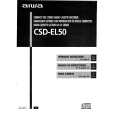 $4.99 CSDEL50 AIWA
Owner's Manual Complete owner's manual in digital format. The manual will be available for download as PDF file aft…
|
|
|
> |
|