|
|
|
Categories
|
|
Information
|
|
Featured Product
|
|
|
 |
|
|
There are currently no product reviews.
 ;
Great manual very clear copied. You are making an incredible job. I appreciate a lot the rapidity and your efficiency. Thanks a lot
 ;
Good pdf of the service manual for this unit. Includes disassembly instructions, full schematics, board layouts, parts lists and diagnostic information. Some information is in the pdf twice (single pages, and split pages), but that could be how it was originally generated by panasonic, or perhaps the idea is to make it eaiser to put onto 8.5 x 11" pages.
Information was exactly what I needed. Delivery was overnight (less than 12 hours) and I was happy with the process.
 ;
5 STARS for FAST DELIVERY, BEST PRICES and QUALITY PRODUCT. Item was exactly as described with superb resolution. Will definitely source all my future requirements from this website. Thanks a lot owner-manual.com!
 ;
OEM manual provided all schematics, board layouts and component specs necessary to facilitate unit maintenance. All pages were clear and readable.
 ;
Good condition and quality. Hard to find anywhere in Internet, only on this site.
Pin No.
36 37 38 39 40 41 42 43 44 45 46 47 48 49 50 51 52 53 54 55 56 57 58 59 60 61 62 63 64
Pin Name
LVDD LCHO LVSS RVSS RCHO RVDD MUTER XVDD XOUT XIN XVSS SBSY EFLG PW SFSY SBCK FSX WRQ RWC SQOUT COIN CQCK RES T11 16M 4.2M T5 CS T1
I/O
� O � � O � O � O
Description
Left channel 1-bit D/A converter power supply. Left channel 1-bit D/A converter output. Left channel 1-bit D/A converter ground. Normally, 0V. Right channel 1-bit D/A converter ground. Normally, 0V. Right channel 1-bit D/A converter output. Right channel 1-bit D/A converter power supply. Right channel 1-bit D/A converter muting output. (Not used) Power supply of crystal oscillator. For the connection of a 16.93MHz crystal oscillator.
I � O O O O I O O I O I I input. I O O O I I I LC78622NE reset input. Test output. Set to open (normally, "L" output.) (Not used) 16.9344MHz output. (Not used) 4.2336MHz output. Test input. A pull-down resistor is incorporated. (Connected to 0V) Chip select input. (Connected to 0V) Test input with no pull-down resistor. (Connected to 0V) Ground of crystal oscillator. Normally, 0V. Subcode block sync signal output. (Not used) C1, C2, single, duplex correction monitor. (Not used) Output of subcodes P, Q, R, S, T, U and W. (Not used) Subcode frame sync signal output. Falls when the subcode is set to the standby state. (Not used) Subcode read-out clock input. Schmitt trigger input. ("L" is applied when not used.) (Connected to 0V) 7.35kHz sync signal output obtained by dividing the oscillator frequency. (Not used) Subcode Q standby output. Read/write control input. Schmitt trigger input. Subcode Q output. Command input from the microprocessor. Command input retrieval clock or subcode retrieval clock input from SQOUT. Schmitt trigger
� 22 �
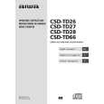
 $4.99 CSDTD26 AIWA
Owner's Manual Complete owner's manual in digital format. The manual will be available for download as PDF file aft…
|
|
 |
> |
|
