|
|
|
Categories
|
|
Information
|
|
Featured Product
|
|
|
 |
|
|
There are currently no product reviews.
 ;
Ordered service manuel for a hard to find plasma tv - your company made it easy to find and purchase - I will use you again
Thanks for your help
 ;
This is a high quality manual with clear schematic and components layout diagrams ; with service procedure included.
;
This service manual for the Kenwood KT-990D was reproduced really well ,is very legible and manual is complete.Combined with the low price paid,in the future,I will be checking Owner-Manuals.com any time I need a manual.
;
When I purchased this manual I had my doubts regarding the quality as the price was so reasonable as compared to other outlets.
The manual itself is of high standard the print is very clear as are the diagrams. Obviously with the diagrams one has to zoom in otherwise it is to small to be able to read.
Overall I am very pleased with the company who delivered as they said and with the manual they supplied.
I occasionally require a manual and now having registered with this company I shall order from them in the future.
;
I was at first dubious about payiong for downloaded manuals but having done so, I was extremely impressed with quality of the two manual I ordered, well worth the small price I paid.
I would highly recommend these to my friends.
ELECTRICAL ADJUSTMENT -4/5
DECK ADJUSTMENT
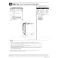
Equipment and tools required Measuring equipment � Wow-flutter meter � Oscillosope � Tset tape:TTA-100/TTA-300(or TTA-310,320) 1. Tape Speed Adjustment Requirements Measuring equipments : wow-flutter meter (frequency counter ) Test Tape: TTA-100 (3KHz) Test point: HP OUT Adjustment point : MOTOR SFR 1) Connect HP OUT to the Wow - flutter meter. 2) Insert the test tape (TTA-100) to Deck2, FWD play back center of the tape and adjust the MOTOR SFR until it becomes 3,000Hz ± 20Hz. 2. Wow � flutter Check Requirements Test tape: TTA-100 (3KHz) Test point: HP OUT Adjustment point : MOTOR SFR 1) Connect the HP OUT to the Wow � flutter meter. 2) Set the indicator to JIS and the mode to W&F(or RMS,UN WTD) of the Wow - flitter meter. 3) Play back thee center of the test tape (TTA-100) and check that it is below 0.35%.
HP OUT
WOW & FLUTTER METER
MOTOR
Hz IN PUT
%
SFR
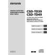
3. Head Azimuth Adjustment Requirements Measuring equipment: Oscilloscope Test Tape: TTA-300 (10KHz) Test point: HP OUT/SP OUT Adjustment point: Head azimuth screw 1) Connect the Test point to the oscilloscope of CH1(Lch) and CH2 (Rch). 2) Set the V mode of the oscilloscope to ADD. 3) Insert the test tape (TTA-330) to Deck1 ,FWD play back the center of the tape and adjustment the head azimuth screw until the waveform of the oscilloscope has reached the maximum when playing back at 10KHz. 4) After the adjustment, bond lock (1600B) the screw.
CH1 TP8 TP9
OSCILLOSCOPE
OUTPUT
CH2
RPH
Head azimuth screw
-38-
 $4.99 CSDTD49 AIWA
Owner's Manual Complete owner's manual in digital format. The manual will be available for download as PDF file aft…
|
|
|
> |
|