|
|
|
Categories
|
|
Information
|
|
Featured Product
|
|
|
 |
|
|
There are currently no product reviews.
 ;
It was very usefull, it is clear the quality is super, the price I paid is very afordable.
Generally speaking Iam very happy with this company.
;
The manual was exactly what I needed, Good quality scans too. superb.
;
I am so happy found this site as it consists of so many Manuls and easy to aquire. This onei s exactly what I wanted and much more as it has info on not only how to use the tuner but how to repair it as well. I will come here 1st before purchasing else where! Thanks owner-manual.com!
;
Top class product, I printed it out on A3 paper and it is clear and very easy to follow.
Cheaper than buying a new radio!
;
is part of the manual is very useful for repairing
Here are circuit diagrams
if there is damage, I recommend using this part of the
a complete list of circuit boards and components
ELECTRICAL ADJUSTMENT -2/5
<MW/LW Adjustment> Make the following preparation for MW/LW adjustment. Preparation � Measuring instruments: Standard Signal Generator (S.S.G)/Loop antenna/Oscilloscope/Millivoltmeter 1) Connect the unit and measuring instruments as shown in the diagram below. 2) Position the loop antenna connected to S.S.G. and the one connected to the unit 60cm apart.
60cm AC MILLIVOLTMETER OSCILLOSCOPE
Standerd Signal Genertaor
CH1 CH 2 OUTPUT CH1 CH2
SET
HP OUT(L) HP OUT(R)
4. IF Adjustment Requirement: � Test point: HP OUT � Adjustment location: L006 1) Set S.S.G. to AM, carrier of 1404KHz with 30% modulation, and source at 1KHz. 2) Tune the receiving frequency of the unit at MW 1404KHz. 3) While monitoring the waveform at 1KHz through the oscilloscope, lower the output level of S.S.G. maximum (till a certain degree of noise is monitored). 4) Adjust L006 so that the millivoltmeter points maximum. 5. MW Tracking Adjustment Requirement: � Test point: HP OUT � Adjustment locations: L003(BAR-ANT), TC001 1) Adjust TC001 so that the mechanical center. 2) Set S.S.G. to AM, carrier 603KHz with 30% modulation, source at 1KHz, and output at maximum. 3) Tune the unit to the receiving frequency at MW 603KHz. 4) While monitoring the waveform at 1KHz through the oscilloscope, lower the output level of S.S.G. maximum (till a certain degree or noise is monitored). 5) Adjust L003(BAR-ANT) so that the millivoltmeter indicates maximum. 6) Set S.S.G. to AM, carrier 1404KHz with 30% modulation, source at 1KHz. 7) Turn the unit to the receiving frequency at MW 1404KHz. 8) While monitoring the waveform at 1KHz through the oscilloscope, lower the output level of S.S.G. maximum (till a certain degree or noise is monitored). 9) Adjust TC001 so that the millivoltmeter indicates maximum. 10) Repeat the above step 2 to 9 two to three time.
-30-
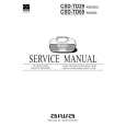 $4.99 CSDTD69 AIWA
Owner's Manual Complete owner's manual in digital format. The manual will be available for download as PDF file aft…
|
|
|
> |
|