|
There are currently no product reviews.
 ;
Very good manual. Plenty of service information including alignment instructions. Clear circuit diagram. Excellent, thank you.
 ;
Good morning, the service manual you sent me was perfect.
Your service and answering are excellent.
I recomend this service.
Best regards.
;
I had been looking everywhere for a proper service manual for this VCR. Everywhere else that has this available for download has a very light version. This is the full service manual with all aspects that would interest anyone looking for the service manual for the AIWA HV-MX100 Worldwide VHS VCR. Great quality (as always). A winner hands down. Best Quality.
;
Top quality manual. Covers all aspects you'd expect in a top quality service manual for this Panasonic VHS VCR. The manual resolution is high. Another top quality manual from the only site worth downloading manuals from! If you're looking for a manual for the PV-9662 VHS VCR, this is the one you'll want to get!
;
complete part-lists and pcb layout, schematic diagram is good enlargable,
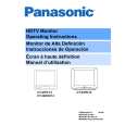
140.0_V B+ voltage check
1. Set the BRIGHT and PICTURE to minimum by using the PICTURE menu. 2. Connect the DVM on TPD144 (D-Board by D2 connector) and cold ground 3. Confirm that B+ voltage is 144.0V ± 1.5V. This voltage supplies B+ to the horizontal output and flyback circuits.
Source voltage chart 120V AC line input. Set the BRIGHT and the PICTURE to minimum by using the PICTURE menu. Use cold or hot ground for the (-) lead of the DVM as needed A-BOARD STBY 7V (BY IC804) A-Board TPP9 MAIN 9V (BY IC875) A-Board TPA7 MAIN 5V (BY IC871) A-Board TPA8 GC 2.5V (BY IC872) A-Board TPA9 STBY 3.3V (BY A1 CONNECTOR) A-Board TPA16 VOLTAGE 7.5 ± 0.6V 9.0V ± 0.5V 5.0V ± 0.3V 2.5V ± 0.2 3.3V ± 0.2V
22
|