|
|
|
Categories
|
|
Information
|
|
Featured Product
|
|
|
 |
|
|
There are currently no product reviews.
 ;
Great to have extra resources for Service Manuals, Now days you can really not trouble shoot efficiently without one , Wayne at IRIONS TV & ELECTRONICS REPAIR Clearwater , Fl. 33755 727-446-7955
 ;
For five bucks you can barely buy a hamburger. Or for the same five bucks you can buy a service manual. Much more useful. (and better for your health, depending on where you buy your hamburgers).
Yes, there are free manual sites out there, but if they don't have what you want, you have to pay.
And five bucks isn't much. Not for full specs, schematics and adjustment and parts replacement procedures.
My only criticism is that grayscale illustrations aren't well rendered, but I've seen worse.
Schematics and text are clear.
I'll be happy to purchase from here again.
Mike
[email protected]
;
Impressively thorough. Even the simple operators manual helped me "fix" one of the 2 CD players in the unit. This unit reads CD's from the top so they should be installed in the magazines "upside down" from typical CD players. The CD player service manual helped me unjam a stuck carriage because somebody transported the box laying down loaded with CD's. A little lens cleaning & the player now works well! Thanks for you help at a great price! Joe
;
I was skeptical at first but later found the manual to be good quality for the price. It took a couple hours to receive the email with the download link, well worth the wait. Thanks.
;
very helpful, I could not have cleaned motherboard and replaced the main fan without it
Precautions
1. Precautions
Follow these safety, servicing and ESD precautions to prevent damage and protect against potential hazards such as electrical shock and X-rays.
1-1 Safety Precautions
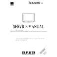
1. Be sure that all of the built-in protective devices are replaced. Restore any missing protective shields. 2. When reinstalling the chassis and its assemblies, be sure to restore all protective devices, including: nonmetallic control knobs and compartment covers. 3. Make sure that there are no cabinet openings through which people�particularly children�might insert fingers and contact dangerous voltages. Such openings include the spacing between the picture tube and the cabinet mask, excessively wide cabinet ventilation slots, and improperly fitted back covers. If the measured resistance is less than 1.0 megohm or greater than 5.2 megohms, an abnormality exists that must be corrected before the unit is returned to the customer. 4. Leakage Current Hot Check (Figure 1-1): Warning: Do not use an isolation transformer during this test. Use a leakagecurrent tester or a metering system that complies with American National Standards Institute (ANIS C101.1, Leakage Current for Appliances), and Underwriters Laboratories (UL Publication UL1410, 59.7). 5. With the unit completely reassembled, plug the AC line cord directly into the power outlet. With the unit�s AC switch first in the ON position and then OFF, measure the current between a known earth ground (metal water pipe, conduit, etc.) and all exposed metal parts, including: antennas, handle brackets, metal cabinets, screwheads and control shafts. The current measured should not exceed 0.5 milliamp. Reverse the powerplug prongs in the AC outlet and repeat the test.
DEVICE UNDER TEST TEST ALL EXPOSED METAL SURFACES 2-WIRE CORD ALSO TEST WITH PLUG REVERSED (USING AC ADAPTER PLUG AS REQUIRED)
LEAKAGE CURRENT TESTER
(READING SHOULD NOT0.5mA) BE ABOVE
EARTH GROUND
Fig. 1-1 AC Leakage Test 6. Antenna Cold Check: With the unit�s AC plug disconnected from the AC source, connect an electrical jumper across the two AC prongs. Connect one lead of the ohmmeter to an AC prong. Connect the other lead to the coaxial connector. 7. X-ray Limits: The picture tube is especially designed to prohibit X-ray emissions. To ensure continued X-ray protection, replace the picture tube only with one that is the same type as the original. Carefully reinstall the picture tube shields and mounting hardware; these also provide X-ray protection. 8. High Voltage Limits: High voltage must be measured each time servicing is done on the B+, horizontal deflection or high voltage circuits. Correct operation of the X-ray protection circuits must be reconfirmed whenever they are serviced. (X-ray protection circuits also may be called �horizontal disable� or �hold-down�.) Heed the high voltage limits. These include the X�ray Protection Specifications Label, and the Product Safety and X-ray Warning Note on the service data schematic.
Samsung Electronics
1-1
|
|
|
> |
|