|
|
|
Categories
|
|
Information
|
|
Featured Product
|
|
|
 |
|
|
There are currently no product reviews.
 ;
A complete manual with all the needed details of calibrations and service instructions about the radio receiver.
A big deal.
Many thanks !
;
Fast delivery and good quality copy. To be recommended
;
Excellent product, very clear print. Detailed circuit and assembly diagrams - this enabled me to repair my CD player with confidence. I highly recommend this site.
;
Fast access, 100% correct and complete service manual
;
just what i was seeking .had a password issue but the review allowed me to circumvent and download was great
LCD DISPLAY
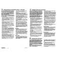
Pin No. 40 41 42 43 44 45 46 47 48 49 50 51 52 53 54 55 56 57 58 59 60 61 62 63 64 65 66 67 68 69 70 71 72 73 74 75 76 77 78 79 80 Pin Name MAIN M CONT SUB M CONT 1 SUB M CONT 2 MODE PL REEL STAND-BY F/R HEAD MS IN LED MI-1 MI-2 MI-3 MO-1 MO-2 MO-3 MO-4 BS CONT NR CONT MTL CONT BEEP RMT IN E-VOL CE E-VOL DO E-VOL CLO DSSA RDS DI DFP IN FLAP IN RDS CLI EJECT IN ACC IN RE1 IN RE2 IN PACK IN REG CPU GND X-OUT X-IN REG OSC VDD RESET O O O O I O O O O I I I I I I I I I � � � I � � I MS/BL switching output. Open when not used Dolby B NR on/off output. Open when not used Metal tape on/off output. Open when not used Beep output (3 kHz, 50 ms) Remote control input. Pulled up when not used CE output to electronic VR (LC75374E) Data output to electronic VR (LC75374E) Clock output to electronic VR (LC75374E) Outputs "H" only when DSSA L/R are operating. RDS data inputPulled down when not used. Detects whether DFP (front panel) is provided or not. Detects whether flap DFP is open or closed. RDS clock inputPulled down when not used NC (pulled down) ACC (accessory power supply) on/off input Rotary encoder input 1. Rotary encoder input 2. Tape insertion status detection input CPU power regulator Ground System clock oscillator System clock oscillator Regulator for oscillator circuit Power supply System reset input O Diode matrix output for initial setting I Diode matrix input for initial setting I/O O O O I I I O I O Main motor control output Sub motor control output-1. Sub motor control output-2. Mode pulse input for tape mechanism. Reel pulse input for tape mechanism. Mechanism Stand-by input Head FWD/REV select output. MS signal input (no music: "H", with music: "L"). Pulled when not used Security LED flashing output ("H": 120-130 ns, 1 cycle: 3 s) Description
17
18
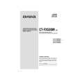 $4.99 CTFX530 AIWA
Owner's Manual Complete owner's manual in digital format. The manual will be available for download as PDF file aft…
|
|
|
> |
|