|
|
|
Categories
|
|
Information
|
|
Featured Product
|
|
|
 |
|
|
There are currently no product reviews.
 ;
thanks a lot.
without the service manual my handycam was going to the trash.
good job, go on.
bye
 ;
This service manual is a good copy of the original, complete and fully readable. It is really useful to repair my Tv set following its clear instructions.
;
Excellent quality. Easy process to download. No issues or problems at all - was exactly what I was looking for and needed. Great service.
;
I was having a hard time finding the problem with this Mackie 1604 unit. I didn't have a schematic. Went looking on the web and found your site and the price was more then reasonable. Ordered it and within the hour had the manual and within 15 minutes had the unit fixed. Best $4.99 I ever spent. Thank you.
Doug
;
This is a service manual in every sense of the word ( French and German versions of the text are included, as well as English..)
There are explanations of the mechanical and electrical functions, plenty of mechanical drawings, and the needed schematics. The quality of the scanning is excellent - all the component values are clearly legible - and very usefully there are pcb component layouts, so you can find a component on the schematic, and then very quicky pinpoint its physical location on the relevant pcb.
I cannot see how I can give this manual any less than the maximum 5 stars! Great value for money, which will pay for itself immediately. Excellent all round!
LED DRIVING
LVDD
La ~ Lg, Lp
LD0 ~ LD7 CPU
IC301 BA612 LED Driver LC1 LC8
Q15 ~ Q18 LED Driver IC17 UPD65611GB-019-3BA P40 KO0 ~ KO3, KO5 P41
LSI14 HD6433294A33F
LG
Gate array
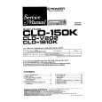
RESET CIRCUIT
When batteries are set or an AC adapter is connected, the reset IC provides a low pulse to the CPU. The CPU then initializes its internal circuit. When the power switch is pressed, the CPU receives a low pulse of POWER signal. The CPU provides APO signal to the power supply circuit and raises RESET signal to +5 V to reset the DSP, the key controller and the gate array.
Battery set VDD RESET Reset IC IC13 RH5VL36AA POWER From power switch APO To power supply circuit -NMI P42
VDD
DVDD Gate Array LSI17 UPD65611GB-019-3BA
DVDD DSP LSI11 HG51B155FD-1
CPU LSI14 HD6433294A33F
-RESET VDD Working Storage RAM LSI15 TC55257DFL-70L DVDD Key Controller LSI16 HG52E35P
� 14 �
|
|
|
> |
|