|
|
|
Categories
|
|
Information
|
|
Featured Product
|
|
|
 |
|
|
There are currently no product reviews.
 ;
This is a top quality manual. You couldn't get better if you had the original and scanned it yourself. Best price on the net as well. Diagrams are clear and complete, text is sharp and easy to read. Granted you don't get the manual the second you click pay, but the few hours you have to wait for it to be available for download isn't a problem at all. This is a very reliable company.
Very VERY pleased with the product, and will buy others. Thanks!
;
In a word AWESOME.
I never expected the quality and abundant content that I got with this manual. Everything you'd ever want to know from a service perspective is found in this manual, along with... as a bonus, operating instructions on how to use the unit. WOW. Very impressed with the quality of the manual. You won't be disappointed if you're looking for the EVS900 service manual.
;
I thank Owen-Manuals.com for the wonderful service rendered to me, and this manual which I purchased helped me a lot in servicing my Denon System, which was lying in a dead state.
Thanks Owner-Manual.com
;
I purchased this manual to repair my Teac set and with the support of this manual I rectified the problem.
Thanks Owner-Manuals.com
;
Excellent service manual, i didn't believe i could find it for such old product, it is very explanatory, managed to fix the disk player!!!
1
2
3
4
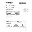
CT-S450S
3. PCB CONNECTION DIAGRAM
NOTE FOR PCB DIAGRAMS:
1. Part numbers in PCB diagrams match those in the schematic diagrams. 2. A comparison between the main parts of PCB and schematic diagrams is shown below. 3. The parts mounted on this PCB include all necessary parts for several destination. For further information for respective destinations, be sure to check with the schematic diagram. BCE B BCE C EB C E Transistor with resistor 3-terminal regulator
Symbol in PCB Diagrams Symbol in Schematic Diagrams Part Name Symbol in PCB Diagrams Symbol in Schematic Diagrams Part Name
A
B C EB C E Transistor Resistor array
4. Viewpoint of PCB diagrams
Connector Capacitor
PDF1004
PDF1035
SIDE A
D DGS
P. C. Board Chip Part
G
SD
G
S Field effect transistor
SIDE B
3.1 POWER SW UNIT and TR 1 UNIT
POWER SW UNIT
SIDE A
B
AC POWER CORD
(RNP1731�B)
C
TR 1 UNIT
POWER TRANSFORMER
SIDE A
(RNP1729�A) To MAIN UNIT J1001
D
5
1 2 3 4
|
|
|
> |
|