|
|
|
Categories
|
|
Information
|
|
Featured Product
|
|
|
 |
|
|
There are currently no product reviews.
 ;
Great Manual. It was exactly what I was looking for
;
I am really satisfied. It was ceap, easy and quick. Te owner manual is a full service book. I got what I expected. Thx
;
The service was good but it just a little late for the download. It seems that it needs to clear the payment but the payment was settled by paypal. As far as my concern, it should be able to download after the confirmation of sold.
;
Great quality manual, fast service, excellent seller... Thanks !!!
;
Great manual and fast service. Download was possible after a few hours.
CTV - 1010XK-XKT
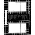
CONTENTS PG. 3. 3-5. 5,6. 6. 1. PRECAUTIONS 1-1. SAFETY PRECAUTIONS 1-2. SERVICING PRECAUTIONS 1-3. PRECAUTION FOR ELECTROSTATICALLY SENSITIVE DEVICES (ESDs) 7. 2. SPECIFICATIONS 8. 3. DESCRIPTIONS OF CONTROLS 9. 4. ALIGNMENT AND ADJUSTMENTS 9. 4-1. PREADJUSTMENT 9-13. 4-2. FACTORY/SERVICE MODE 13-17. 4-3. OTHER ADJUSTMENTS 17. 5. USING DEVICES AND DESCRIPTION 17-20. 5-1. MAIN SIGNAL PROCESSOR (TDA8842) 21. 5-2. VERTICAL OUTPUT (TDA8356) 22. 5-3. TRIPLE VIDEO OUTPUT AMPLIFER (TDA6107Q) 23,24. 5-4. L4964 25,26. 5-5. TDA2007A 27. 5-6. VIDEO SELECT SWITCH (NJM2235L) 28,29. 5-7. TELETEX (SAA5281P) 30,31. 5-8. POWER CIRCUIT (TEA2262) 32. 6. TECHNICAL STUDY (SMPS OPERATION) 32. 6-1. STARTING MODE-STAND BY MODE 32,33. 6-2. NORMAL MODE 33. 6-3. SECURITY FUNCTIONS 34. 6-4. OVERVOLTAGE DETECTION 34. 6-5. CURRENT LIMITATION OF THE POWER TRANSISTORS 34. 6-6. RESTART OF THE POWER SUPPLY 34. 7. TROUBLE SHOOTING 35. 7-1. NO POWER 35. 7-2. NO RASTER 36. 7-3. NO SOUND 37. 8. BLOCK DIAGRAM 38. 9. DIFFERENT PARTS LIST 39,40. 10. PCB LAYOUT 41-46. 11. PARTS LIST CIRCUIT DIAGRAM
2
|
|
|
> |
|