|
|
|
Categories
|
|
Information
|
|
Featured Product
|
|
|
 |
|
|
There are currently no product reviews.
 ;
This manual is very well presented and after printing out looks about as close to an original as I think you can get. The quality is second to none.
The content of the manual is comprehensive and I think it would be well suited to an audio repair professional which I'm not but I did find it very informative and helpful.
The cost of the manual is more than covered by the money I'll save when I change the keep memory battery now I have the relavant info.
Very pleased with my purchase and can recommend it wholeheartedly as I can other manuals I've downloaded from this site.
Regards
Limey Alex
 ;
Complete manual including mechanical part in good pdf quality. Shaded greys of the pcb due to pdf not perfect but usable.
;
Nice pdf file of the manual sent promptly. Thanks.
;
Complete MFG Service Manual at a good price FAST !
;
Downloaded the manual, reasonably straightforward, pretty much exactly as advertised.
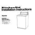
POWER SUPPLY TROUBLESHOOTING GUIDE
It is highly recommended that a variable isolation transformer which can monitor current be used. (Alternatively a variable AC source which monitors current will do). Read directions below before power is added! 2] Check for any defective parts while the secondary rectifying diodes are disconnected D021, D015, D016, and D020 perform a diode check in both forward and reverse directions through a tester. 3] Remove the following components and check for defects: snubber diode (D051), switching FET (Q001), source resistor (R014), and control transistor (Q002).
CHECK
Repair method
Repair method #2
Connect unit to the isolation transformer and slowly increase the AC supply while monitoring the YES current, if it draws too much current (Be ware fuse is rated for 1.0 amps), then turn off supply and do repair method #1. NO Check whether the primary rectifying DC of the Switching power supply NO has an output. (Reading should be about 168V.) YES With the primary DC working check NO the secondary 5V. YES Are the 44V, 12V and 5V lines higher than normal? NO Although the secondary 5V is working, are any of the other voltages higher than normal (44V and 12V voltages)? NO There is no problem on the SW power supply. YES #4
Check the fuse 1.0A (F001), primary rectifying diodes (D001-D004) as possible problems. Remove the above mentioned parts and check them. The circuit which turns on switching FET (Q001) may be regarded as a possible cause, even if the load at the secondary side is shorted, it can't be detected because switching FET (Q001) isn't operating. Perform check according to the steps 1] and 2] of repair method #1 and check the following parts: (Remove the part from PCB) Switching FET (Q001), source resistor (R014), gate resistor (R008), and start resistor (R004 and R005).
#1
#2
#3
Repair method #3
A circuit to turn on switching FET (Q001) may not work and this may be regarded as a cause of trouble. Even if the load at the secondary side is short-circuited, it cannot be detected because switching FET (Q001) does not turn on. Therefore, perform check according to the steps 1] and 2] of the repair method #1 and execute the under-mentioned parts breakage check. (Remove the part from PCB.) switching FET (Q001), source resistor (R014), control shunt regulator (Q031), gate resistor (R008), and start resistor (R004 and R005).
YES
#5
Repair method #1
(Power must be off) 1] Short circuit in the secondary side. Check diode D021, D015, D016, and D020, switching FET (Q001), control transistor (Q002), diode (D006), and resistor (R014) replace as necessary. Disconnect 44V diode (D021), 12V diode (D015), 5V diode (D016), and 12V diode (D020). Check the load continuity of 44V line, 12V line, and 5V line through a tester (resistance range). If the tester indicates a lower resistance value around 0 ohm, the line is short-circuited. Before repairing the switching power supply, find out the short-circuited area of such line and repair it. If the tester does not indicate any low resistance value (around 0 ohm), no load is short-circuited and there is no problem.
Repair method #4
The feedback circuit which is monitored by the output of voltage may not work and this may be regarded as a possible cause, remove control transistor Q002 and check for defects. More over, a photo coupler (IC001) and transistor (Q031) may be defective, replace any defective parts with factory originals.
Repair method #5
If the output voltage of the secondary side is slightly high, the line load may be in the �OPEN� state and this may be regarded as a cause of trouble. If there is no output voltage on the secondary side, the rectifying diodes (D021), (D015), and (D020) may be defective.
1-8-1
U29.5L4HTR
|
|
|
> |
|