|
|
|
Categories
|
|
Information
|
|
Featured Product
|
|
|
 |
|
|
There are currently no product reviews.
 ;
It took about 24-hours after my payment before I was able to get to the download. Apparently, payment processing is not 100% automated. That is no big deal, just be aware of that going in.
After I got to it, it was in good shape, easy to read, etc. Not some cheap FAX copy looking thing.
Also, this site was the cheapest I found. Another Plus!
 ;
Good price, very legible manual, exactly what I needed -- but had to wait a day to actually get the download of the manual. Would have preferred to download it immediately after payment rather than waiting for someone to "process" my order. I was surprised that I had to wait that long.
;
As the only source for this manual it rather rank quite high since it is well scanned and perfectly readable.
;
the manual is in good quality and it's in pdf. manual was send in less then 24h.
regards
mike
;
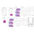
I would not plug this machine in without finding a manual like this. In addition to setup and normal operating instructions, it has troubleshooting flowcharts, diagrammed mechanical adjustments, and schematics to beat the band. The tech I hand it to would be thrilled to find solder side PCB diagrams with component outlines superimposed, pinouts for every IC chip, and line drawings of transistors, with labeled legs.
As for printing quality, this may be a copy of a copy, but even the finest print when enlarged is very legible. There is a bit of grayed print over a few pages, as if a wet page were placed over it, but the print is still very legible. If you could borrow an original manual and get it printed and bound for 4 to 6 times the cost, you could get better quality. In that case you wouldn't be here. For price, utility, and availability I am rating this manual highly.
D
Vorbereitende Arbeiten
GB
Preparatory steps
Bevor Sie den elektrischen Abgleich durchführen, müssen Sie folgende Vorbereitungen treffen: Höhen - Einstellung ........................................................................ 0 Bass - Einstellung .......................................................................... 0 Fader - Einstellung (nicht Lübeck/Luxembourg) ............................ 0 Balance - Einstellung ..................................................................... 0 Loudness - Einstellung (DSC Menü) .............................. 1 oder OFF
Observe the following preparations before performing the electrical alignment: Treble adjustment .......................................................................... 0 Bass adjustment ............................................................................ 0 Fader adjustment (not Lübeck/Luxembourg) ................................. 0 Balance adjustment ....................................................................... 0 Loudness adjustment (DSC menu) .................................... 1 or OFF
Lautsprecheranschlu�
Der Lautsprecherausgang mu� mit 4 � abgeschlossen sein.
Loudspeaker connections
The loudspeaker output must be terminated with 4 �.
Abgleichhinweise
Wellenbereich: FM = 87,5 MHz - 108,0 MHz (100 kHz automatische Suchlaufschritte) (50 kHz manuelle Suchlaufschritte) MW = 531 kHz - 1602 kHz (9 kHz automatische Suchlaufschritte) (9 kHz manuelle Suchlaufschritte) LW = 153 kHz - 279 kHz (9 kHz automatische Suchlaufschritte) (1 kHz manuelle Suchlaufschritte)
Notes on alignment
Waveband: FM = 87.5 MHz - 108.0 MHz (100 kHz automatic search steps) (50 kHz manual search steps)
MW = 531 kHz - 1602 kHz (9 kHz automatic search steps) (9 kHz manual search steps) LW = 153 kHz - 279 kHz (9 kHz automatic search steps) (1 kHz manual search steps)
Für den Abgleich müssen Sie die Stationstasten mit folgenden Frequenzen programmieren: Taste FM1 MHz MW kHz LW kHz 1 98,1 531 162 2 98,1 558 198 3 98,1 558 198 4 98,1 1521 5 98,1 1602 6 91,1
The station preset push-buttons have to be be programmed for the alignment to the following frequencies : Push-button 1 FM1 MHz MW kHz LW kHz 98.1 531 162 2 98.1 558 198 3 98.1 558 198 4 98.1 1521 5 98.1 1602 6 91.1
AM + FM - Abgleich:
Den AM- und FM-Abgleich müssen Sie durchführen, wenn bei einer Reparatur frequenzbestimmende Bauteile ausgetauscht oder verstellt wurden. Nach Reparatur-/ Abgleicharbeiten müssen die Geräteparameter neu programmiert werden.
AM + FM alignment:
The AM and FM alignment has to be carried out if components that determine the circuit's frequency have been replaced or detuned. After a repair or alignment job the basic parameters of the product have to be reprogrammed.
-
-
Abschirmung
Der HF-Abgleich mu� mit Unterdeckel erfolgen. Hierzu ist es ratsam da� Sie an die Me�punkte Leitungen anzulöten. Führen Sie die Leitungen nach oben oder seitlich aus dem Gerät heraus.
Radio-shielding
The r-f alignment has to be performed with the bottom cover in place. It is advisable to solder wires to the measuring points and provide access from the top of the the main board or out through holes in the side of the frame.
-6-
|
|
|
> |
|