|
|
|
Categories
|
|
Information
|
|
Featured Product
|
|
|
 |
|
|
There are currently no product reviews.
 ;
Detailed SONY CFD980 Service Manual at an easy to find one stop shopping. Make my radio hobby technically interesting. Thanks.
 ;
Excellent service from Owner-Manuals.com, good prices and quick turn around. The supplied PDF was good enough quality to be enlarged sufficiently to read component values.
;
Very complete shop manual. It contains everything needed to troubleshoot bascially any problem. Instructions, diagrams, schmeatics, illustrations... it's all there. Highly recommended!
;
Great product, very good quality, found all needed information. Thanks
;
Excellent quality, helped to fix problem. Thank you very much!!!!
2 ADJUSTMENTS AND CHECKS
2-1 Test Mode
2-1-1 Getting into Test Mode
While holding down the INPUT SELECTOR � and � buttons, power on the unit and hit the DIGITAL FILTER button repeatedly.
2-2 Audio System
Setting
CLOCK MODE: PLL AES3 INPUT: SINGLE DIGITAL FILTER: FIR DIGITAL IN: Fs=44.1kHz, FullBit � If you intend to use a digital output of the P-70 or others for connection to the digital input, use a digital signal that is not upconverted.
2-1-2 Version Display
When the test mode is activated, the microcomputer version information, "uComVer X.XX", is displayed. Then, at each press of the INPUT SELECTOR � button, the RDOT version information, "RDOTver XXXX", and the RAM version information, "RAMversionXX", are displayed in sequence.
2-2-1 DC Offset Adjustment
1. Set the OUTPUT SELECT switch on the rear panel to "XLR". 2. Apply a digital signal to the DIGITAL IN and check to see that the input indicator turns on and that a sampling frequency shows in the display. (Check of the lock status.) 3. Turn the OUTPUT LEVEL control counterclockwise, so that the output level is �� (as shown by "___._" in the display). 4. Measure the DC offset voltage between pins 2 (+) and 3 (�) of LINE OUT (XLR). Adjust VR303 (L) and VR403 (R) on ANALOG PCB for ±5mV.
XLR pin assignments XLR����
2-1-3 FL Grid Check
After displaying a series of version information, pressing the INPUT SELECTOR � button activates the grid check mode and the display reads "GridChecking". Turn the OUTPUT LEVEL control to check to see that the grids turn off one after another. Continue to turn the OUTPUT LEVEL control to check to see that the grids turn on one after another.
2-1-4 FL Segment Check
When the FL grid check is done with, press the INPUT SELECTOR � button to activate the segment check mode. Turn the OUTPUT LEVEL control to check to see that the dot matrix turns on by dot.
2-1-5 LED Check
VR403 VR303
When the FL segment check is done with, press the INPUT SELECTOR � button to activate the LED check mode. The display reads "LEDCHECK RDT". Turn the OUTPUT LEVEL control to check to see that each LED turns on.
2-1-6 Resetting EEPROM
When the LED check is done with, press the INPUT SELECTOR � button and "! EEPRESET !" is displayed. Press the DIGITAL FILTER button and the display changes to read "EEPSAVE OK" and the ROM is reset.
ANALOG PCB
�3�
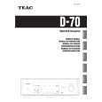 $4.99 D70 TEAC
Owner's Manual Complete owner's manual in digital format. The manual will be available for download as PDF file aft…
|
|
|
> |
|