|
There are currently no product reviews.
 ;
A complete and well done copy of the manual, at a not expansive price!
The delivery of the manual is very fast.
Thank you for all
;
Perfect quality. Was able to fix speed drifting on my Sansui Turntable using the service manual instructions for PLL adjustment.
;
I am very happy regarding the online purchase of this manual from Owner-Manuals.com as with this I could set right my Denon CD player and Amplifier.
I once again sincerely thank them for the prompt service which was rendered to me.
N. Shanker
;
More than pleased with my prurchase, very good product for the price.
;
Manual-link came 30 minutes after having paid for an extremely rare (40 years old) item (sony icr-120) and helped me to get the radio rework again. So really good help for me, fast and reliable delivery and -taken that into consideration- a very reasonable price for that service. So thanks again! Mike, Germany
1
2
3
4
TS5, BCT-1510, BCT-1520, BCT-1530
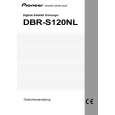
4. PCB CONNECTION DIAGRAM
4.1 FRONT ASSY
A
B FRONT ASSY
SIDE A
NOTE FOR PCB DIAGRAMS :
1. Part numbers in PCB diagrams match those in the schematic diagrams. 2. A comparison between the main parts of PCB and schematic diagrams is shown below.
Symbol In PCB Diagrams Symbol In Schematic Diagrams B CEB CE Part Name
BCE B BCE D DGS GSD GS C EB C E
Transistor
Transistor with resistor
Field effect transistor
Resistor array
3-terminal regulator
B
3. The parts mounted on this PCB include all necessary parts for several destinations. For further information for respective destinations, be sure to check with the schematic diagram. 4. View point of PCB diagrams.
Connector
Capacitor
SIDE A
P.C.Board
Chip Part
SIDE B
C
A CN7002
D
(BNP1353-B)
28
B
1 2 3 4
|