|
There are currently no product reviews.
 ;
The quality is quite good and clear. Nothing of the informations inside is lost during the digitalizing process
 ;
Very good service, fast downloads and good manuals.
;
Good qulity. Even as it is an old manual (from 1991-1992) it has a good scanned quality and is complete, including user's manual, disassembly intructions, diagrams and schematics, ajustments, troubleshooting and parts list, as usual with SONY manuals and Owner-manuals service.
;
tres bon document
cela a permis de verifier la connection de l'ecran
merci
salutations
;
The manual was of good quality with high resolution schematic diagrams.
1
2
3
4
TS5, BCT-1510, BCT-1520, BCT-1530
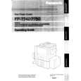
4. PCB CONNECTION DIAGRAM
4.1 FRONT ASSY
A
B FRONT ASSY
SIDE A
NOTE FOR PCB DIAGRAMS :
1. Part numbers in PCB diagrams match those in the schematic diagrams. 2. A comparison between the main parts of PCB and schematic diagrams is shown below.
Symbol In PCB Diagrams Symbol In Schematic Diagrams B CEB CE Part Name
BCE B BCE D DGS GSD GS C EB C E
Transistor
Transistor with resistor
Field effect transistor
Resistor array
3-terminal regulator
B
3. The parts mounted on this PCB include all necessary parts for several destinations. For further information for respective destinations, be sure to check with the schematic diagram. 4. View point of PCB diagrams.
Connector
Capacitor
SIDE A
P.C.Board
Chip Part
SIDE B
C
A CN7002
D
(BNP1353-B)
28
B
1 2 3 4
|