|
There are currently no product reviews.
 ;
Best help everywhere i got from here. My audio medicinman was happy to get this manual from me. So he could repair my pioneer perfectly. Thanks
R O
;
It was very usefull, it is clear the quality is super, the price I paid is very afordable.
Generally speaking Iam very happy with this company.
;
The manual was exactly what I needed, Good quality scans too. superb.
;
I am so happy found this site as it consists of so many Manuls and easy to aquire. This onei s exactly what I wanted and much more as it has info on not only how to use the tuner but how to repair it as well. I will come here 1st before purchasing else where! Thanks owner-manual.com!
;
Top class product, I printed it out on A3 paper and it is clear and very easy to follow.
Cheaper than buying a new radio!
1
2
3
4
TS5, BCT-1510, BCT-1520, BCT-1530
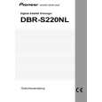
4. PCB CONNECTION DIAGRAM
4.1 FRONT ASSY
A
B FRONT ASSY
SIDE A
NOTE FOR PCB DIAGRAMS :
1. Part numbers in PCB diagrams match those in the schematic diagrams. 2. A comparison between the main parts of PCB and schematic diagrams is shown below.
Symbol In PCB Diagrams Symbol In Schematic Diagrams B CEB CE Part Name
BCE B BCE D DGS GSD GS C EB C E
Transistor
Transistor with resistor
Field effect transistor
Resistor array
3-terminal regulator
B
3. The parts mounted on this PCB include all necessary parts for several destinations. For further information for respective destinations, be sure to check with the schematic diagram. 4. View point of PCB diagrams.
Connector
Capacitor
SIDE A
P.C.Board
Chip Part
SIDE B
C
A CN7002
D
(BNP1353-B)
28
B
1 2 3 4
|