|
|
|
Categories
|
|
Information
|
|
Featured Product
|
|
|
 |
|
|
There are currently no product reviews.
 ;
I am proud of you. In the future, I benefited from your services.
;
I found this manual to be complete in every detail. Besides the schematic it has a complete set of alignment instructions which are easy to understand. It also includes a complete parts list as well as an explanation of how the power supply and safety shutdown circuits operate. Even a schematic of the tuner is included.
 ;
The product was good and just what I needed, however I had moderate difficulty with the down load because the sight would not recognize my pass word. I was finally given a direct link to the manual and that worked.
;
Very quick and easy website to use and fast download of manual, quality of manual is excellent and will be pleased to use this service again in the future, thanks so much!
;
It is an very good and clear scanned service manual.
very recommended.
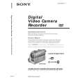
DCR-DVD200/DVD200E/DVD300
COVER
1-1. SERVICE NOTE
1. POWER SUPPLY DURING REPAIRS
SECTION 1 SERVICE NOTE
In this unit, about 10 seconds after power is supplied to the battery terminal using the regulated power supply (8.4V), the power is shut off so that the unit cannot operate. This following two methods are available to prevent this. Take note of which to use during repairs. Method 1. Use the AC power adaptor (AC-L15, AC-VQ800 etc.). Method 2. Connect the servicing remote commander RM-95 (J-6082-053-B) to the LANC jack, and set the commander switch to the �ADJ� side.
2.
1 2 3 4 5 6 7
TO TAKE OUT A CASSETTE WHEN NOT EJECT (FORCE EJECT)
Refer to page 2-3 to remove the front panel assembly. Refer to page 2-4 to remove the cabinet (R) assembly. Refer to page 2-16 to remove the battery panel section. Refer to page 2-17 to remove the EVF block. Remove the VC-310 board. Refer to page 2-21 to remove the lens block and the accessory shoe. While pushing the portion A in the direction of the arrow, push the OPEN switch in the direction of the arrow and open the disc cover.
Open switch
Plunger
A
MD-097 board
3.
NOTES ON HANDLING THE OPTICAL PICK-UP
4.
The laser diode may suffer electrostatic breakdown because of the potential difference generated by the charged electrostatic load, etc. on clothing and the human body. During repair, pay attention to electrostatic breakdown and also use the procedure in the printed matter which is included in the repair parts. The flexible board is easily damaged and should be handled with care.
PRECAUTION FOR CHECKING EMISSION OF LASER DIODE
Laser light of the equipment is focused by the object lens in the optical pick-up so that the light focuses on the reflection surface of the disc. Therefore, be sure to keep your eyes more then 30 cm apart from the object lens when you check the emission of laser diode.
1-1
|
|
|
> |
|