|
|
|
Categories
|
|
Information
|
|
Featured Product
|
|
|
 |
|
|
There are currently no product reviews.
 ;
This service manual for the Kenwood KT-990D was reproduced really well ,is very legible and manual is complete.Combined with the low price paid,in the future,I will be checking Owner-Manuals.com any time I need a manual.
;
When I purchased this manual I had my doubts regarding the quality as the price was so reasonable as compared to other outlets.
The manual itself is of high standard the print is very clear as are the diagrams. Obviously with the diagrams one has to zoom in otherwise it is to small to be able to read.
Overall I am very pleased with the company who delivered as they said and with the manual they supplied.
I occasionally require a manual and now having registered with this company I shall order from them in the future.
;
I was at first dubious about payiong for downloaded manuals but having done so, I was extremely impressed with quality of the two manual I ordered, well worth the small price I paid.
I would highly recommend these to my friends.
;
reasonable price for the schematic - the service is perfect, all as expected and pointed by instructions - good scan of the original plans - thank you!
;
Manual was just as described!!! I odered it and in less than a day was able to download it and the text was clear and pages were all complete just as the original manual was. Purcashed this for a friend and they were more than happy. Perfect all around!
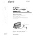
DCR-DVD200/DVD200E/DVD300
COVER
1-1. SERVICE NOTE
1. POWER SUPPLY DURING REPAIRS
SECTION 1 SERVICE NOTE
In this unit, about 10 seconds after power is supplied to the battery terminal using the regulated power supply (8.4V), the power is shut off so that the unit cannot operate. This following two methods are available to prevent this. Take note of which to use during repairs. Method 1. Use the AC power adaptor (AC-L15, AC-VQ800 etc.). Method 2. Connect the servicing remote commander RM-95 (J-6082-053-B) to the LANC jack, and set the commander switch to the �ADJ� side.
2.
1 2 3 4 5 6 7
TO TAKE OUT A CASSETTE WHEN NOT EJECT (FORCE EJECT)
Refer to page 2-3 to remove the front panel assembly. Refer to page 2-4 to remove the cabinet (R) assembly. Refer to page 2-16 to remove the battery panel section. Refer to page 2-17 to remove the EVF block. Remove the VC-310 board. Refer to page 2-21 to remove the lens block and the accessory shoe. While pushing the portion A in the direction of the arrow, push the OPEN switch in the direction of the arrow and open the disc cover.
Open switch
Plunger
A
MD-097 board
3.
NOTES ON HANDLING THE OPTICAL PICK-UP
4.
The laser diode may suffer electrostatic breakdown because of the potential difference generated by the charged electrostatic load, etc. on clothing and the human body. During repair, pay attention to electrostatic breakdown and also use the procedure in the printed matter which is included in the repair parts. The flexible board is easily damaged and should be handled with care.
PRECAUTION FOR CHECKING EMISSION OF LASER DIODE
Laser light of the equipment is focused by the object lens in the optical pick-up so that the light focuses on the reflection surface of the disc. Therefore, be sure to keep your eyes more then 30 cm apart from the object lens when you check the emission of laser diode.
1-1
|
|
|
> |
|