|
|
|
Categories
|
|
Information
|
|
Featured Product
|
|
|
 |
|
|
There are currently no product reviews.
 ;
Great product. Recieved it fast...exactly as advertised.
;
Manuals were delivered promptly and were correct as advertised. No issues with the download link which was provided promptly after everything was processed. Very pleasant experience
;
Paid for service manual & got the download fast - worth a visit if you need a service manual
;
It's the manual, I am searching for. Now I am able to repair my Braun A501.
 ;
Great service manual. Unfortunately on page no. 41 there are some details which i can't read.
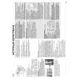
DCR-DVD200/DVD200E/DVD300
2-29.LB-084 BOARD (REMOVING OF THE EVF)-2
4
Visibility knob (40)
VF slide cabinet (upper) assembly To raise the VF slide cabinet (upper) assembly, insert a flat head (-) screwdriver into the position shown by the arrow. VF slide cabinet (upper) assembly
2A 1 Tapping screw (M1.7 � 3.5) 5 C
3 B
2 A
VF slide cabinet (lower)
2 Open the lock of the VF slide cabinet (lower) in the direction of the arrow A, 3 while slanting the VF slide cabinet (upper) assembly in the direction of the arrow B, 4 remove the Visibility knob (40) from the VF slide cabinet (lower), and 5 remove the VF slide cabinet (upper) assembly by sliding it in the direction of the arrow C.
VF slide cabinet (lower)
RE-ASSEMBLING THE VF SLIDE CABINET
1 VF slide assembly
2 Align the dotted portion of the VF slide assembly with the dotted line of the VF slide cabinet (lower).
VF slide cabinet (lower)
When re-assembling, slide the Visibility knob (40) to the fully right-end beforehand. Visibility knob (40) When re-assembling is completed, the VF slide cabinet (upper) assembly and the VF slide cabinet (lower) are assembled as shown. VF slide cabinet (upper) assembly
3 Slide the VF slide cabinet assembly up to the position in the direction of the arrow where the two claws are locked.
4 Tapping screw (M1.7 � 3.5)
VF slide cabinet (lower) VF slide cabinet (lower) Two claws
2-19
|
|
|
> |
|