|
|
|
Categories
|
|
Information
|
|
Featured Product
|
|
|
 |
|
|
There are currently no product reviews.
 ;
It's a good manual, this one it's a scan from the original factory service manual, great quality 100% readeable. definetely it worths what I paid for.
 ;
A good manual! fast service and good qualityi for pdf document.
thanks!
;
Very helpful and complete manual. Maybe only one negative is schematics have sometimes unreadable name of the parts. But it's not a big problem.
;
Excellent high quality schematics brought my old Heidelberg back to life. Fast download at a reasonable price. Thanks.
;
This document is just what I was looking for, it´s very useful, it contains adjustment procedures for the final stage of the power amp and also
has a complete wiring diagram and description of the main semiconductors used in the design.
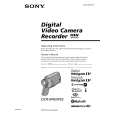
DCR-IP45/IP45E/IP55/IP55E
3.
DISCHARGING OF THE FLASHLIGHT POWER SUPPLY CAPACITOR
The capacitor (C4207) of the flash unit (FL-2960) is charged up to the maximum 300V potential. There is a danger of electric shock by this high voltage when the flash unit (FL-2960) is handled by hand. The electric shock is caused by the charged voltage which is kept without discharging when the main power of the unit is simply turned off. Therefore, the remaining voltage must be discharged as described below. 3-1. PREPARING THE SHORT JIG To preparing the short jig. a small clip is attached to each end of a resistor of 1k�/1W (1-215-869-11). Wrap insulating tape fully around the reads of the resistor to prevent electric shock.
1 k �/1 W
Wrap insulating tape
3-2. DISCHARGING THE CAPACITOR 1 Remove the power supply (Battery or AC power adaptor). 2 Short-circuit between TP4201 of the flash unit (FL-2960) and the GND (Mechanism chassis) with the short jig about 10 seconds.
TP4201
C4270 Short jig 1k �/1W resistor (1-215-869-11)
4.
COAXIAL CONNECTOR OF THE BT CABLE
When the coaxial connector of the BT cable isn�t pulled out vertically toward the board, the connector may be damaged. So, when disconnecting the connector, be sure to take the connector of the BT cable, and pull it out vertically toward the board.
BT cable
BT-003 board
1-2
|
|
|
> |
|