|
|
|
Categories
|
|
Information
|
|
Featured Product
|
|
|
 |
|
|
There are currently no product reviews.
 ;
Great to have extra resources for Service Manuals, Now days you can really not trouble shoot efficiently without one , Wayne at IRIONS TV & ELECTRONICS REPAIR Clearwater , Fl. 33755 727-446-7955
 ;
For five bucks you can barely buy a hamburger. Or for the same five bucks you can buy a service manual. Much more useful. (and better for your health, depending on where you buy your hamburgers).
Yes, there are free manual sites out there, but if they don't have what you want, you have to pay.
And five bucks isn't much. Not for full specs, schematics and adjustment and parts replacement procedures.
My only criticism is that grayscale illustrations aren't well rendered, but I've seen worse.
Schematics and text are clear.
I'll be happy to purchase from here again.
Mike
[email protected]
;
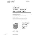
Impressively thorough. Even the simple operators manual helped me "fix" one of the 2 CD players in the unit. This unit reads CD's from the top so they should be installed in the magazines "upside down" from typical CD players. The CD player service manual helped me unjam a stuck carriage because somebody transported the box laying down loaded with CD's. A little lens cleaning & the player now works well! Thanks for you help at a great price! Joe
;
I was skeptical at first but later found the manual to be good quality for the price. It took a couple hours to receive the email with the download link, well worth the wait. Thanks.
;
very helpful, I could not have cleaned motherboard and replaced the main fan without it
(Original : Page 18)
Note :Regarding the text with underline, refer to the original manual (D mechanism).
3-13. T HARD BRAKE, L BRAKE, S BRAKE ARM, S HARD AND CC SWITCH COVER 1. Removing 1) Refer to 1-1. to lift the cassette compartment assembly. 2) Remove the CC switch cover. Note: Take note of two clawsA and B. 3) Refer to 3-10. to remove the LED base assembly. 4) Remove the tension spring1 from the side of LS chassis, then remove the S brake arm, torsion spring and S hard. 5) Remove the tension spring 2 from the side of L brake, remove the T hard brake together with the tension spring 2. 6) Remove the L brake. 2. Attaching 1) Attach the S hard and torsion spring to the S brake arm. Note: Pay attention to attach the spring and S hard, and the hooking position of spring. 2) Hook the tension spring1 to the S brake arm, then attach the S brake arm to the LS chassis. Note: Pay attention to direction appoint at spring hook. 3) Hook the tension spring1 to the side of LS chassis. 4) Attach the L brake. 5) Hook the tension spring2 to the T hard brake , then attach the T hard brake to the LS chassis with hooking the tension spring2 to the L brake. 6) Refer to 3-10. to attach the LED base assembly. 7) Attach the CC switch cover so that claws A and B are into holes A and B each. 8) Refer to 1-1. to attach the cassette compartment assembly.
Hooking the tension spring 1.
Tension spring
Hooking the torsion spring.
S brake arm S brake arm
Hooking the tension spring 2.
S brake arm L brake
S hard Torsion spring CC down switch
T hard brake Hole B T hard brake
Tension spring
Hole A
Claw B Claw A
CC switch cover LS chassis
_9_
|
|
|
> |
|