|
There are currently no product reviews.
 ;
Had everything I needed. Onyly took a few hours after paid for by PayPal. The copy was very readable.
 ;
Hi
First, thank you very much for the fast delivery.
I'm really satisfied with your manual. I could find everything, I needed.
I appreciate your service.
Regards from Germany PB
;
Everything you need: schematic, circuit explanation, operating/testing instructions. Awesome.
;
Correct and accurate service manual for that Siemens (Nordmende) TV. Price is worthwhile as the Manual is fully usable.
;
Just what I needed to repair my CT-F600, clear pdf, easy to tread and navigate
3-1-3. Adjusting Connectors Some of the adjusting points of the video section are concentrated at VC-213 board CN910. Connect the measuring instruments via the CPC-13 jig (J-6082-443-A). The following table lists the pin numbers and signal names of CN910. Pin No. 1 2 3 4 5 6 7 8 9 10 Signal Name SWP AFC F0 BPF MONI RF AGC IN PB RF REG GND RF AGC OUT VC RF SWP EVF BL EVF BL 4.6V Pin No. 11 12 13 14 15 16 17 18 19 20 Signal Name EVF VCO EVF VG DV RF SWP RF IN CAP FG RF MON TMS TCK TDO TDI
CN910 1 20
Screw driver (�)
Table 5-3-1.
Cover
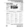
3-1-4. Connecting the Equipment Connect the measuring instruments as shown in Fig. 5-3-2 and perform the adjustments.
Connecting the TV Monitor and Regulated Power Supply
Battery terminal
Main Unit Regulated power supply 8.4 +0.1Vdc _ VIDEO
TV monitor
Connect when using the camera mode or playing back. VIDEO terminal
Fig. 5-3-2.
5-47
|