|
|
|
Categories
|
|
Information
|
|
Featured Product
|
|
|
 |
|
|
There are currently no product reviews.
 ;
Excellent copy that was delivered within 12 hours and solved my problem.
 ;
I did not have the manual for a Whirl Pool gas dryer, therefore I purchased it from Owner-manuals. This is exactly what I needed. Thank you for the service.
;
I was so pleased to get the owner`s manuel within one hour! Thanks again.
Regards
Werner
;
Finding the owners manual for my Pioneer CRWM62R is greatly appreciated. I had searched several other web sites with no success. Although my manual was not listed on your site for immediate download, I recevied an email within a few hours that my ower's manual was posted for me. I had no difficulty downloading the manual for my 20 year old multi-cassette player. Owner Manuals provides a service that is valuable, easy-to-use, accurate , efficient, and priced fairly. I thank you.
;
Excellent manual - just what I needed. Although currently available only in German, their are lots of pictures which makes it all very clear.
SERVICE NOTE
1. POWER SUPPLY DURING REPAIRS
Battery switch
In this unit, about 10 seconds after power is supplied (8.4 V) to the battery terminal using the service power cord (J-6082-223-A), the power is shut off so that the unit cannot operate. This following two methods are available to prevent this. Take note of which to use during repairs.
Method 1.
Connect the servicing remote commander RM-95 (J-6082-053-B) to the LANC jack, and set the remote commander switch to the �ADJ� side.
Method 2.
Press the battery switch of the battery terminal using adhesive tape, etc.
Battery terminal 3 Battery terminal #
Method 3.
Use the DC IN terminal. (Use the AC power adaptor.)
DC IN terminal
Battery SIG terminal
2.
1 2 3 4 5 6
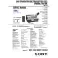
TO TAKE OUT A CASSETTE WHEN NOT EJECT (FORCE EJECT)
Refer to 2-4 to remove the front panel assembly. Refer to 2-6 to remove the cabinet (L) assembly. Refer to 2-7 to remove the cabinet (R) assembly. Refer to 2-13 to remove the battery panel assembly. Disconnect CN4401 of VC-235 board. Add +5 V from the DC POWER SUPPLY and unload with a pressing the cassette lid.
7 Pull the timing belt in the direction of the arrow with a pincette while pressing the cassette lid (take care not to damage) to adjust the bending of a tape.
Press the cassette lid to rise the cassette compartment Pincette [DC power supply] (+5V)
Timing belt
8 Let go your hold the cassette lid and rise the cassette compartment to take out a cassette.
Loading motor
Disconnect CN4401 of VC-235 board. Timing belt Adjust the bending of a tape
�4�
|
|
|
> |
|