|
|
|
Categories
|
|
Information
|
|
Featured Product
|
|
|
 |
|
|
There are currently no product reviews.
 ;
Great manual...really saved me. The only problem is that I thought I would be able to download it directly when I paid for it but never received the download instructions until the next morning. The board trace pages were somewhat light also: really need to turn up the contrast on the printer before printing them. The schematic page was great; very clear! Well worth the money.
 ;
I've been in the electronic business for a long time. I used to buy Sam's Photofact for my needs which intailed having to go to the store and paying about $20 for a package of 3 different units so I was forced to buy more than I needed just to get one.
Owner manual is just at your keyboard and the information is almost instantansouly and the cost is very reasonable. Easy to print out if needed or simply read off of the screen. The larger the screen the better for obvious reasons.
;
Very good manual, at a very good price. Received in a timely manner
;
Only thу cover has poor quality, internal material has excellent quality - exactly what I needed
Thanks!
;
Had everything I needed. Onyly took a few hours after paid for by PayPal. The copy was very readable.
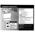
3-1-3. Adjusting Connectors Some of the adjusting points of the video section are concentrated at VC-213 board CN910. Connect the measuring instruments via the CPC-13 jig (J-6082-443-A). The following table lists the pin numbers and signal names of CN910. Pin No. 1 2 3 4 5 6 7 8 9 10 Signal Name SWP AFC F0 BPF MONI RF AGC IN PB RF REG GND RF AGC OUT VC RF SWP EVF BL EVF BL 4.6V Pin No. 11 12 13 14 15 16 17 18 19 20 Signal Name EVF VCO EVF VG DV RF SWP RF IN CAP FG RF MON TMS TCK TDO TDI
CN910 1 20
Screw driver (�)
Table 5-3-1.
Cover
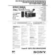
3-1-4. Connecting the Equipment Connect the measuring instruments as shown in Fig. 5-3-2 and perform the adjustments.
Connecting the TV Monitor and Regulated Power Supply
Battery terminal
Main Unit Regulated power supply 8.4 +0.1Vdc _ VIDEO
TV monitor
Connect when using the camera mode or playing back. VIDEO terminal
Fig. 5-3-2.
5-47
|
|
|
> |
|