|
|
|
Categories
|
|
Information
|
|
Featured Product
|
|
|
 |
|
|
There are currently no product reviews.
 ;
Wanting to repair a neighbours tape recorder I needed the necessary information, it makes it easier. Although the service manual is described as "Language : English" To my dismay I found that it is entirely written in German, a language I do not understand. At least I now have the schematics which will help of sorts. I may not use this service again due to the laguage difficulty after all when it states English you do not expect it to be entirely in another language.
 ;
GOOD SERVICE MANUAL.I ALWAYS BUY THERE IF I FIND WHAT I AM LOKING
;
Good quality (clearly readable) manual, I'm glad I could find it here, at a bargain price!
;
Speedy transaction with a quick download. Awesome hassle-free service.
;
very poolite and healpful secure transaction thanks allot
3. Battery End Check (VC-240/241 board) Check the battery end voltage. Mode Camera recording and VTR playback Subject Arbitrary
Note: It is normal though the following symptoms appear during the battery end check. 1) The message of �FOR InfoLITHIUM BATTERY ONLY� on the LCD or viewfinder screen. 2) The tally lamp is flashing.
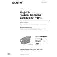
Connection: 1) Connect the regulated power supply and the digital voltmeter to the battery terminal as shown in Fig. 5-3-4. Checking method: 1) Adjust the output voltage of the regulated power supply so that the digital voltmeter display is 6.0 ± 0.1Vdc. 2) Turn off the power supply. 3) Turn on the HOLD switch of the adjustment remote commander. 4) Turn on the power supply. 5) Load a cassette, and set to the camera recording mode. 6) Decrease the output voltage of the regulated power supply so that the digital voltmeter display is 5.5 ± 0.1Vdc. 7) Record the camera signal for a minute. 8) Playback the recorded section and check that the playback picture and sound are normal.
Regulated power supply
+
5.5 ± 0.01 Vdc
+
+
Digital volt meter
Fig. 5-3-4.
5-50
|
|
|
> |
|