|
|
|
Categories
|
|
Information
|
|
Featured Product
|
|
|
 |
|
|
There are currently no product reviews.
 ;
Very good copy in a 54 pages PDF archive. This is my sixth purchase here. :)
;
Another excellent buy! File too clear and explanatory.
 ;
A manual hard to find. It was very helpful to restore my device.
;
I am very grateful for this manual. Without it could not repair my receiver.
;
excellent work as always you do cheap, fast net and clean. you do an incredible service......thanks!
SERVICE NOTE
1. POWER SUPPLY DURING REPAIRS
In this unit, about 10 seconds after power is supplied to the battery terminal using the regulated power supply (8.4V), the power is shut off so that the unit cannot operate. These following two methods are available to prevent this. Take note of which to use during repairs. Method 1. Connect the servicing remote commander RM-95 (J-6082-053-B) to the LANC jack, and set the commander switch to the �ADJ� side. Method 2. Use the DC IN terminal. (Use the AC power adaptor (AC-L10, AC-VQ800 etc. ))
2.
1 2 3 4 5 6 7 8 9 0 qa
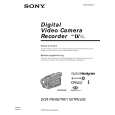
TO TAKE OUT A CASSETTE WHEN NOT EJECT (FORCE EJECT)
Refer to 2-4. to remove the top cabinet assembly. Refer to 2-4. to remove the front panel block assembly. Refer to 2-4. to remove the cabinet (R) block assembly. Refer to 2-6. to remove the battery panel section. Refer to 2-6. to remove the VC heat sink. (DCR-TRV20/TRV20E model only) Refer to 2-6. to remove DD-137 board. Open the VC-240/241 board. Refer to 2-9. to remove the two screws (M1.7 � 2.5) with which the MD frame assembly is fixed on the CS frame assembly. Refer to 2-9. to remove the mechanism deck and VC-240/241 board. Remove the CN006 (27P 0.3 mm) of the VC-240/241 board. Supply +4.5V from the DC power supply to the loading motor and unload with a pressing the cassette compartment.
DC power supply (+4.5Vdc)
: Unloading : Loading Disconnect from CN006 (27P) of VC-240/241 board
CN006
VC
-2
4
0/
241
boa
rd
Loading motor
�8�
|
|
|
> |
|