|
|
|
Categories
|
|
Information
|
|
Featured Product
|
|
|
 |
|
|
There are currently no product reviews.
 ;
Excellent printing quality.
A complete and very usefull service manual with all details.
GREAT SERVICE AT VERY LOW PRICE!
A+++++++++++++++++++++++++
;
Excellent printing quality.
A complete and very usefull service manual with all details.
GREAT SERVICE AT VERY LOW PRICE!
A+++++++++++++++++++++++++
;
Thank you for providing quickly a manual so old! very good job clear and understandable!
;
Excellent printing quality.
A complete and very usefull service manual with all details.
GREAT SERVICE AT VERY LOW PRICE!
A+++++++++++++++++++++++++
;
Excellent printing quality.
A complete and very usefull service manual with all details.
GREAT SERVICE AT VERY LOW PRICE!
A+++++++++++++++++++++++++
DCR-TRV25/TRV27
COVER
1-1. SERVICE NOTE
1. POWER SUPPLY DURING REPAIRS
SECTION 1 SERVICE NOTE
In this unit, about 10 seconds after power is supplied to the battery terminal using the regulated power supply (8.4V), the power is shut off so that the unit cannot operate. This following two methods are available to prevent this. Take note of which to use during repairs. Method 1: Use the AC power adaptor (AC-L10, AC-VQ800 etc.). Method 1: Connect the servicing remote commander RM-95 (J-6082-053-B) to the LANC jack, and set the commander switch to the �ADJ� side.
2.
1 2 3 4 5 6 7 8 9
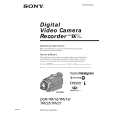
TO TAKE OUT A CASSETTE WHEN NOT EJECT (FORCE EJECT)
Refer to 2-3 to remove the front panel assembly. Refer to 2-5 to remove the top cabinet assembly. Refer to 2-6 to remove the cabinet (R) assembly. Refer to 2-7 to remove the battery panel section. Remove the EVF block. Open the VA-117 board. Disconnect CN1010 (27P, 0.3mm) of VC-281 board. Open the cassette lid. Supply +4.5V from the DC power supply to the loading motor and unload with a pressing the cassette compartment.
Loading motor
CN1010 VC-281 board
DC power supply (+ 4.5V)
1-1
|
|
|
> |
|