|
|
|
Categories
|
|
Information
|
|
Featured Product
|
|
|
 |
|
|
There are currently no product reviews.
 ;
Pioneer CDXP23S is an old model and has been top useful for me to find this Manual. CD Player is still repaired.
;
Inventory (Stock): a rather extensive list of service manuals, which are hard to find, especially 15+ yrs old.
Pricing: very reasonable.
Delivery/Response: Very Prompt delivery of product: Placed order and received download access within 1.5hrs.
Service Manual: a rather complete OEM service manual (15.5MB pdf file size). Scan quality was very good, accept for a few circuit board diagrams that were dark; Zooming, however, clarified the image. Has the required information for servicing the LD Player.
;
Perfect copy of a necessary document and my Sonic Modulator is repaired!
;
Excellent replacement for original Manual. Worth every cent ! I am totally satisfied!
;
Only in this place I could find this manual. Very complete and very clear. PDF is a very good quality and easily read. Thank you. I was very useful.
Videoson & ltd.
SERVICE NOTE
1. POWER SUPPLY DURING REPAIRS
In this unit, about 10 seconds after power is supplied to the battery terminal using the regulated power supply (8.4V), the power is shut off so that the unit cannot operate. This following two methods are available to prevent this. Take note of which to use during repairs. Method 1. Use the AC power adaptor (AC-L10, AC-VQ800 etc.). Method 2. Connect the servicing remote commander RM-95 (J-6082-053-B) to the LANC jack, and set the commander switch to the �ADJ� side.
2.
TO TAKE OUT A CASSETTE WHEN NOT EJECT (FORCE EJECT)
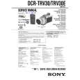
1 Open the flash. (If the flash cannot be opened i the position as shown, remove the top cabinet reffering to section 2-4 and open the flash.) 2 Refer to 2-3 to remove the front panel assembly. 3 Refer to 2-4 to remove the upper cabinet assembly. 4 Refer to 2-4 to remove the cabinet (R) assembly. 5 Refer to 2-5 to remove the battery panel section. 6 Refer to 2-5 to remove the VC heat sink and EVF section. 7 Open the VC-264 board. 8 Refer to 2-6 to remove the three screws with which the MD frame assembly is fixed. 9 Remove the mechanism deck and VC-264 board. 0 Disconnect CN006 (27P, 0.3mm) of VC-264 board. qa Supply +4.5V from the DC power supply to the loading motor and unload with a pressing the cassette compartment.
DC power supply (+4.5Vdc)
: Unloading : Loading Disconnect from CN006 (27P) of VC-264 board
CN006
VC-2
6
4
b
oa
r
d
Loading motor
�7�
|
|
|
> |
|