|
|
|
Categories
|
|
Information
|
|
Featured Product
|
|
|
 |
|
|
There are currently no product reviews.
 ;
We received the manual in a timely manner and it was exactly what we were expecting. Excellent replacement for original Service Manual.
All schematics are very legible. We are really satisfied.
;
We received the manual in a timely manner and it was exactly what we were expecting. Excellent replacement for original Service Manual.
All schematics are very legible. We are really satisfied.
;
We received the manual in a timely manner and it was exactly what we were expecting. Excellent replacement for original Service Manual.
All schematics are very legible. We are really satisfied.
;
We received the manual in a timely manner and it was exactly what we were expecting. Excellent replacement for original Service Manual.
All schematics are very legible. We are really satisfied.
;
We received the manual in a timely manner and it was exactly what we were expecting. Excellent replacement for original Service Manual.
All schematics are very legible. We are really satisfied.
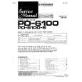
4-2. HCL Arm Assembly, Loading Motor Assembly
1. Removal procedure
1) 2) 3) 4) Hook the HC arm spring in the direction of the arrow B. Remove the HCL arm assembly 2 from the loading motor assembly 4. Remove the screw (M1.4 � 2.5) 3. Remove the three claws of the loading motor assembly 4 from the mechanism chassis assembly in the direction of the arrow A.
2. Attachment procedure
1) 2) 3) 4) Coat the worm shaft and gear of the loading motor assembly 4 with grease. Insert the three claws of the loading motor assembly 4 into the groove on the mechanism chassis assembly. Attach the screw (M1.4 � 2.5) 3. Tightening torque: 0.078 ± 0.01 N�m (0.8 ± 0.1 kgf�cm) Check the position of the HCL arm assembly 2 and the HC drive arm. Then attach the HCL arm assembly 2 to the loading motor assembly 4. Hook the HC arm spring 1 on the notch of the loading motor assembly 4. Clean the drum assembly. (Refer to section 2-1.)
5) 6)
Hook the HC arm spring on the notch of the loading motor assembly.
2 HCL arm assembly
Drive pin
3 Screw (M1.4 � 2.5)
Remove the loading motor assembly in the direction of the arrow A.
A polarity exists. The marked side has a red line.
4 Loading motor assembly
A
B
1 Pull and hook the HC arm spring in the direction of the arrow B.
Three claws Mechanical chassis assembly
When attaching it, coat the hatched portion with grease. Loading motor assembly (rear view)
Cover sheet Drive pin
HC drive arm
Loading motor assembly
Fig. 4-2.
� 15 �
|
|
|
> |
|