|
|
|
Categories
|
|
Information
|
|
Featured Product
|
|
|
 |
|
|
There are currently no product reviews.
 ;
Original well scanned manual. Got the job done. Microwave problem found & corrected. For $5 and a new magnitron from ebay, it was a cheap and good the first shot fix. Electrical schematics allowed me to mage sure every thing else was ok before cutting and order for parts. Hard to live without.
;
I was very skeptical of this website, I have never downloaded manuals before. I put it on the AMEX and payed through Paypal to ensure protection. I got the manual exactly as described and now I can replace the filter capacitor for this amp. Great Price, others selling for 12.99 or more and this is the same manual. I will search out this website for other manuals. Thank you
;
Manual was reasonably easy to follow. I am not an engineer or know much about electronics but with the manuals help I was able to figure out the problem, identify the part required for the repair. Replacement part cost around $30. Whilst replacing the part I was telling myself, "this aint gonna work cos it seems far too easy". Took about 15 minutes to do and my plasma TV works a treat. Would never have been able to do this without the service manual.
;
It is OK, this manual help me to repair my dynacord
 ;
Good manual. Even it is an old printed manual, it is well scanned and complete, with all drawings, schematics and parts list. Very good return for the cost.
DCR-TRV40/TRV40E/TRV50/TRV50E
4.
DISCHARGING OF THE FLASHLIGHT POWER SUPPLY CAPACITOR
The power supply capacitor of the flash unit is charged up to the maximum 300V potential. There is a danger of electric shock by this high voltage when the capacitor is handled by hand. The electric shock is caused by the charged voltage which is kept without discharging when the main power of the unit is simply turned off. Therefore, the remaining voltage must be discharged as described below. 4-1. PREPARING THE SHORT JIG To preparing the short jig. a small clip is attached to each end of a resistor of 1k�/1W (1-215-869-11). Wrap insulating tape fully around the reads of the resistor to prevent electric shock.
1 k�/1 W
Wrap insulating tape.
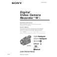
4-2. DISCHARGING THE CAPACITOR 1 Remove the power supply (Battery or AC power adaptor). 2 Open the cassette lid (grip cabinet). 3 Remove the two screws with which the grip cover is fixed. 4 Remove the grip cover. 5 Remove the insulation sheet. 6 Short circuit between 3 and # terminal of the capacitor with the short jig about 10 seconds.
3 Two screws, tapping (M1.7 � 5)
4 Grip cover
5 Insulation sheet
2 Open the cassette lid.
6
Flash unit
Short jig
Power supply capacitor
Note for installing the grip cover When installing the grip cover, insert it in the claws of the grip cabinet.
Two claws
Grip cover
1-2
|
|
|
> |
|