|
|
|
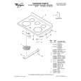
Categories
|
|
Information
|
|
Featured Product
|
|
|
 |
|
|
There are currently no product reviews.
 ;
Fast, clear and useful. Important for me: the manual is in German.
 ;
Very good quality. Some parts are not fully readable, but the fundamental ones are fine.
;
very good quality readable manual,printed off very well.
;
The manual was very accurate for the part that I was changing, I was able to order the correct part and had no issues with the replacement procedure. However, I was expecting to have more detailed repairs for the lower drive unit.
;
I needed the manual immediately and I got it immediately. I couldn't find this manual anywhere else on the net. The site was easy to traverse, and the price was very reasonable. I'll definitely be back for any future needs.
4-16. Rotary Switch, Cam Relay Gear, Change Gear Assembly, Timing Belt
Before replacing the timing belt, remove the guide rail T2 and capstan motor. (Refer to 4-4.)
1. Removal procedure
1) 2) 3) 4) 5) 6) 7) Remove the LS chassis block assembly. (Refer to 4-10.) Remove the guide lock plate (T), pinch pressure assembly and eject arm. (Refer to 4-15.) Remove the cam relay gear 1. Remove the timing belt 2. Remove the HLW cut (0.98 � 3 � 0.25) 3 and change gear assembly 4. Remove the four solderings 5 and remove the FP-299 flexible wiring board 6. Push up the dowel of the rotary switch 7 from the bottom of the mechanism chassis assembly and remove the rotary switch in the direction of the arrow.
2. Attachment procedure
1) Insert the dowel of the rotary switch 7 into the hole on the mechanism chassis assembly and attach the rotary switch clockwise. Align the FP-299 flexible wiring board 6 with the reference hole on the mechanism chassis and solder the flexible wiring board to the rotary switch 7 (at four locations). Attach the change gear assembly 4 with the HLC cut (0.98 � 3 � 0.25)3. Attach the timing belt 2.
Note: There must be a clearance between the rotary switch 7 and timing belt 2.
2)
3) 4) 5)
6) 7) 8)
Attach the cam relay gear 1. The in-phase markings of the rotary switch 7, cam relay gear (2) and cam relay gear (1) must be aligned. Attach the guide lock plate (T), pinch pressure assembly and eject arm. (Refer to 4-15.) Attach the LS chassis block assembly to the mechanical chassis. (Refer to 4-10.) Clean the shaft of the capstan motor. (Refer to 2-2.)
7 Remove the rotary switch in the direction of the arrow.
Attachment direction The ribs must be facing upward. Dowel
Clearance must exist between the claw of the rotary switch and the belt.
1 Cam relay gear (2)
SETTING THE GEAR POSITION
3 HLW cut (0.98 � 3 � 0.25)
Hole of mechanism chassis Rotary switch Cam relay gear (2) Cam relay gear (1)
Belt must be completely free from twist or stain when it is installed
4 Change gear assembly
5 Remove the four solderings
Bend here at right angles.
2 Timing belt
Cam relay gear (1)
6 FP-299 flexible board
Align the holes.
When attaching it, coat the hatched portion with grease.
Fig. 4-16.
� 29 �
|
|
|
> |
|