|
|
|
Categories
|
|
Information
|
|
Featured Product
|
|
|
 |
|
|
There are currently no product reviews.
 ;
Manual was just as described!!! I odered it and in less than a day was able to download it and the text was clear and pages were all complete just as the original manual was. Purcashed this for a friend and they were more than happy. Perfect all around!
 ;
Excellent service and prompt delivery. But it's not a manual - only 4 pages wiring diagrams.
Thanks.
;
The manual I purchased was exactly what I needed to repair my Toshica television. The manual contained schematics and troubleshooting information that was very helpful.
;
Il download del Service Manual JVC HR 4100 non é stato eseguito
;
The Service Manual was just as expected, complete with schematics and I was able to download it in less than an hour after I ordered it. The only problem with these is that the schematics are hard to read due to the small font. I could remedy this by printing them on a larger printer.
D-E221/E223 SECTION 1 SERVICE NOTE
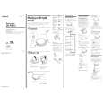
NOTES ON HANDLING THE OPTICAL PICK-UP BLOCK OR BASE UNIT The laser diode in the optical pick-up block may suffer electrostatic breakdown because of the potential difference generated by the charged electrostatic load, etc. on clothing and the human body. During repair, pay attention to electrostatic breakdown and also use the procedure in the printed matter which is included in the repair parts. The flexible board is easily damaged and should be handled with care. Precautions for Checking Emission of Laser Diode Laser light of the equipment is focused by the object lens in the optical pick-up so that the light focuses on the reflection surface of the disc. Therefore, be sure to keep your eyes more then 30 cm apart from the object lens when you check the emission of laser diode. Before Replacing the Optical Pick-Up Block Please be sure to check throughly the parameters as par the �Optical Pick-Up Block Checking Procedures� (Part No.: 9-960-02711) issued separately before replacing the optical pick-up block. Note and specifications required to check are given below. � FOK output : IC601 eg pin When checking FOK, remove the lead wire to disc motor. � RF signal P-to-P value : 0.5 ± 0.1 Vp-p � The repairing grating holder is impossible. Laser Diode Checking Methods During normal operation of the equipment, emission of the laser diode is prohibited unless the upper lid is closed while turning ON the S801. (push switch type) The following two checking methods for the laser diode are operable. � Method: Emission of the laser diode is visually checked. 1. Open the upper lid. 2. With a disc not set, turn on the S801 with a screwdriver having a thin tip as shown in Fig.1. or TAP802 is shorted as shown in Fig.2. Note: Do not push the detection lever strongly, or it may be bent or damaged. 3. Press the > N button. 4. Observing the objective lens, check that the laser diode emits light. When the laser diode does not emit light, automatic power control circuit or optical pick-up is faulty. In this operation, the objective lens will move up and down 5 times along with inward motion for the focus search.
O FF ON
detection lever
detection lever
S801
main board
Fig. 1
� MAIN BOARD � (SIDE A)
E223:FR MODEL
S803
S803 HOLD
TAP802
� MAIN BOARD � (SIDE B)
8 1
9
16
OPEN
S805
S801
1-681-329-
Fig. 2
3
 $4.99 D-E221 SONY
Owner's Manual Complete owner's manual in digital format. The manual will be available for download as PDF file aft…
|
|
|
> |
|