|
|
|
Categories
|
|
Information
|
|
Featured Product
|
|
|
 |
|
- SERVICING NOTES
- GENERAL
- DISASSEMBLY
- SERVICE MODE
- ELECTRICAL ADJUSTMENTS
- DIAGRAMS
- Block Diagram - MAIN Section
- Block Diagram - POWER SUPPLY Section
- IC Pin Function Description
- Printed Wiring Board
- Schematic Diagram
- EXPLODED VIEWS
- ELECTRICAL PARTS LIST
There are currently no product reviews.
 ;
Great price, Quick delivery, the document was very usefull A+++++++++++++++
;
This service Manual for my JVC AV29BF10EES is very helful. Everything is show in detailed diagrams!!!! If you need really good source of information for this type JVC you are on the right place. I am satisfied and very glad for this excellent book. Thank you.
;
Great service, great value like always!!!
Some of the writing is a bit blur but all is usable.
A+++++++++++++++++
;
Great service manua!
Always great value and fast service A++++++++++++++++++
;
Excellent Service manual, good quality scans, quick service and very good value. Well reccomended ! All good.
SECTION 4 SERVICE MODE
Service Mode (Service program) The equipment is provided with a service program built in the microcomputer, like conventional models. Service program operation methods are described in the following.
PLAY MODE Tracking servo and sled servo are turned ON REPEAT/ENTER Tracking gain-up mode while pressing
4. By pressing the ^ key, focus is turned ON from focus searching while entering CLV-S. (draw-in mode) Without disc, focus searching is repeated continuously. 5. By pressing the PLAY MODE key, tracking servo, sled servo and CLV-A (servo in PLAY) are turned ON. 6. When step 4 and 5 are performed, playing begins. No muting is ON in the service mode. 7. By pressing the p key, all servos (focus, tracking and sled) are turned OFF. However, the disc motor revolves for a while by inertia. � Step 3 (Resetting of service mode) 1. Be sure to disconnect the external power supply and remove the solder bridge at the TEST terminals connected before in setting. 2. The set thus becomes available for normal operation.
HOLD c Be sure to turn OFF the HOLD switch (If ON, all the LCD indication and LED are light up)
� MAIN BOARD (Side A) � = (FR) The optical pick-up is moved inwardly + (FF) The optical pick-up is moved outwardly
^ (PLAY/PAUSE) Focus is tuned ON to effect draw-in mode p (STOP)
[All servos are turned OFF]
Descriptions in [ ] indicate major operations in the service mode. For more informatrion, see Step 2.
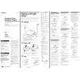
Fig. 1 Layout of each key
� Step 1 (Service mode setting methods) 1. Turn OFF the HOLD switch with external power supply disconnected. (power is not applied to the set) 2. Solder across the TEST terminals (TAP802). (pin %¢, IC801 (ESPSL/TEST) is grounded) 3. Connect an external power supply. Thus, the set is switched to the service mode. � Step 2 (Operation in the service mode) 1. Once the service mode is effected, the LCD displays 5 indications each of which is repeatedly displayed. However, the following operations can be activated even if LCD indication is effected. 2. By pressing the + or = key, the optical pick-up is movable inwardly or outwardly. However, if this is activated, tracking servo and sled servo are turned OFF, so it can be turned ON by pressing the PLAY MODE key if required. 3. By pressing the REPEAT/ENTER key, the tracking gain-up mode becomes active.
TAP802 (TEST)
Fig. 2 Location of Test terminal
�8�
 $4.99 D-E555 SONY
Owner's Manual Complete owner's manual in digital format. The manual will be available for download as PDF file aft…
|
|
|
> |
|