|
|
|
Categories
|
|
Information
|
|
Featured Product
|
|
|
 |
|
- GENERAL
- SERVICE NOTE
- DISASSEMBLY
- SERVICE MODE
- ELECTRICAL ADJUSTMENTS
- DIAGRAMS
- Block Diagram
- Printed Wiring Boards
- Schematic Diagram
- IC Pin Function Description
- EXPLODED VIEWS
- ELECTRICAL PARTS LIST
There are currently no product reviews.
 ;
Great product, helped me to restore vintage walkman cassette.
Just some pictures could be little bit more sharp and contrast
Thank you
;
I love older radio's and the service manuals that are sometimes hard to find. Was able to find a manual quite easily on this site.
;
Thank you for your shop manual! Your help was very useful - the device is repaired! Once again - Thank you! I wish you a successful business! Edward (Russia).
;
It was a great experience,instead of purchasing a new Stereo Amplifier ,in just minutes i repaired my old one and that was thaks to the manual I have purchased from you.
Thanks again.
Samuel Alter
;
Das ging ja sehr unkompliziert hat bestens geklappt und die Quallität ist auch noch gut.
Vielen Dank dafür.
SECTION 5 ELECTRICAL ADJUSTMENTS
Precautions for Adjustment 1. Before beginning adjustment, set the equipment to service mode. After the completion of adjustment, be sure to reset the service mode. For more information, see �Service Mode (service program) � on page 8. 2. Perform adjustments in the order given. 3. Use YEDS-18 disc (Part No.: 3-702-101-01) unless otherwise indicated. 4. Power supply voltage requirement: DC2.5 V in battery terminal VOLUME knob : Minimum RESUME switch : OFF ESP switch : OFF AVLS switch : NORMAL HOLD switch : OFF Before Beginning Adjustment Set the equipment to service mode (See page 8) and check the following. If there is an error, repair the equipment. � Checking of the sled motor 1. Open the upper panel. 2. Press the + and = keys and check that the optical pickup can move smoothly without sluggishness or abnormal noise in innermost periphery n outermost periphery n innermost periphery + :The optical pick-up moves outwardly. = :The optical pick-up moves inwardly. � Checking of focus searching 1. Open the upper panel. 2. Press the ^ key. (Focus searching operation is activated continuously.) 3. Check the object lens of the optical pick-up for smooth up/ down motion without sluggishness or abnormal noise. 4. Press the p key. Check that focus searching operation is deactivated. If not, again press the p key slightly longer. VCC Adjustment Adjustment Procedure:
digital voltmeter (DC range) MAIN board TP401 (VCC) (See page 11) + �
Focus bias Check Condition: � Hold the set in horizontal state. Check Procedure:
oscilloscope (AC range) MAIN board TP522 (RFO) TP520 (VC) (See page 11) 2k�
+ �
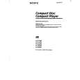
1. Set the equipment to service mode stop state. (See page 8.) 2. Connect the oscilloscope to the test point TP522 (RFO) of the MAIN board. 3. Move the optical pick-up to the center by pressing the + and = keys. 4. Put the disc (YEDS-18). 5. Press the ^ key. From focus searching, focus is turned ON while entering CLV drawing-in mode. Tracking and sled are turned OFF. 6. Press the PLAY MODE key. (Both tracking and sled are turned ON.) 7. Check the oscilloscope waveform is as shown below. A good eye pattern means that the diamond shape (�) in the center of the waveform can be clearly distinguished. RF SIGNAL REFERENCE WAVEFORM (EYE PATTERN)
VOLT/DIV : 200 mV (With the 10:1 probe in use) TIME/DIV : 500 ns
RF level 1.0 ± 0.2V
To watch the eye pattern, set the oscilloscope to AC range and increase the vertical sensitivity of the oscilloscope for easy watching.
8. Stop revolving of the disc motor by pressing the p key. 9. After the completion of adjustment, reset service mode. (See page 8.) Check Location: MAIN Board (See page 11.)
1. Set the equipment to service mode stop state. (See page 8.) 2. Connect the digital voltmeter to TP401 (VCC) of the MAIN board. 3. Adjust RV401 on the MAIN board so that the reading on digital voltmeter goes 2.75± 0.05 V. 4. After the completion of adjustment, reset service mode. (See page 8.) Adjustment Location: MAIN board (See page 11)
�9�
 $4.99 D-E700 SONY
Owner's Manual Complete owner's manual in digital format. The manual will be available for download as PDF file aft…
|
|
|
> |
|