|
There are currently no product reviews.
 ;
It was magic after so many years to still be able to source this info. It was equally amazing to return my Pioneer receiver to it near new sound quality AFTER NEARLY 30 YEARS! Thank you for this ability!
;
Very quick and easy website to use and fast download of manual, quality of manual is excellent and will be pleased to use this service again in the future, thanks so much!
 ;
Easy and secure way to get a complete service manual of a vintage hifi component. Only some parts of the print copy are dificult to read. Nice price!
;
The manual is an excellent reproduction with complete schematics, made troubleshooting and repair a simple process.
;
Up to now you are the BEST! Prompt-efficient and so reasonable ! I have been after SONY service manual for quite some time !Thank you very much ! I can recomend your service to
all my collegagues ! V.Bergfield .
CX-977
Fig. 5: RFRP and RFCT circuit
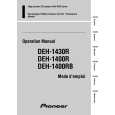
5) SBAD Signal Circuit unit
In this unit, outputs from the photo detector, namely, E and F are processed through the addition amplifier. That is, E and F are added together and (E+F) signal is output from #15 pin of IC101 (TA2153FN), as SBAD signal. This SBAD signal, along with Focus Error signal, is used as one of the conditions that the system uses to internally judge Focus ON/OFF based on them. Also, SBAD signal is used to detect defects: defects that may be detected when the Pickup passes a scratch on the disk, for instance.
Fig. 6: SBAD circuit
5
|